For efficient vehicle operation in harsh conditions, it’s crucial to have a clear understanding of the essential components that make up the equipment. Proper maintenance and knowing how to assemble and disassemble each piece ensures optimal performance when needed most. This section breaks down the critical elements, their functions, and how they interact with each other to form a cohesive system.
Identifying the individual parts is key to diagnosing any potential issues and performing effective repairs. Having a visual reference of the layout allows for quick identification and easier troubleshooting. Whether it’s for professional use or personal upkeep, understanding the structure of these elements provides confidence and improves overall functionality.
In this article, we will explore how to interpret the various segments, ensuring you can fully comprehend the structure and enhance your ability to work with these tools efficiently. With the right knowledge, even complex systems become manageable, and you can ensure a smooth experience during maintenance and usage.
Understanding the Vehicle Clearing System
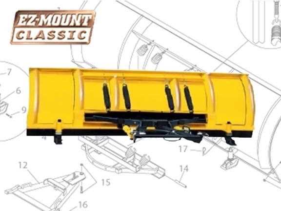
Effective clearing systems are designed to handle tough conditions, providing vehicles with the ability to move efficiently through snow and debris. These systems consist of several integrated components that work together to achieve the desired performance. Familiarity with the structure of these systems ensures smoother operation and helps identify potential issues before they become serious problems.
Key Components and Functions

At the core of the clearing system lies a robust mechanism that enables both flexibility and power. Key components such as the lifting mechanisms, control units, and hydraulic systems allow for precise movements and adjustments. Each part plays a distinct role, contributing to the overall effectiveness of the machine. Understanding how each piece interacts with others will help you maintain optimal performance throughout the system’s life cycle.
Maintaining and Troubleshooting the System
Proper maintenance of these systems is essential for reliable operation. Regular inspections and knowing how to troubleshoot common issues can prevent downtime and improve safety. The control system is particularly important, as it links all other elements and ensures they function as one unit. Understanding this connection helps identify issues early, saving both time and resources in the long run.
Essential Components of Vehicle Clearing Systems
A reliable vehicle clearing system relies on several vital elements that contribute to its functionality and efficiency. Each component serves a specific purpose, whether it’s to enable movement, enhance control, or ensure durability in harsh conditions. Understanding these key elements helps ensure proper operation and longevity of the entire system, ensuring that it performs as intended when needed most.
Hydraulic System and Control Mechanisms
The hydraulic system plays a central role in the operation of the clearing mechanism. It enables the lifting, angling, and lowering of the attachment with precision. Paired with control mechanisms, it ensures that operators can adjust the system’s position effortlessly. These elements must be maintained regularly to avoid issues such as leaks or sluggish movement, which can impact performance.
Structural Frame and Mounting Points
The frame forms the foundation of the system, supporting the weight of all other components while ensuring stability and durability. The mounting points are critical for securing the attachment to the vehicle, ensuring that it remains firmly in place during use. Any wear and tear on the frame or mounting points could lead to unsafe operation or damage to other parts of the system, making regular checks and repairs necessary.
How to Interpret the Vehicle System Blueprint
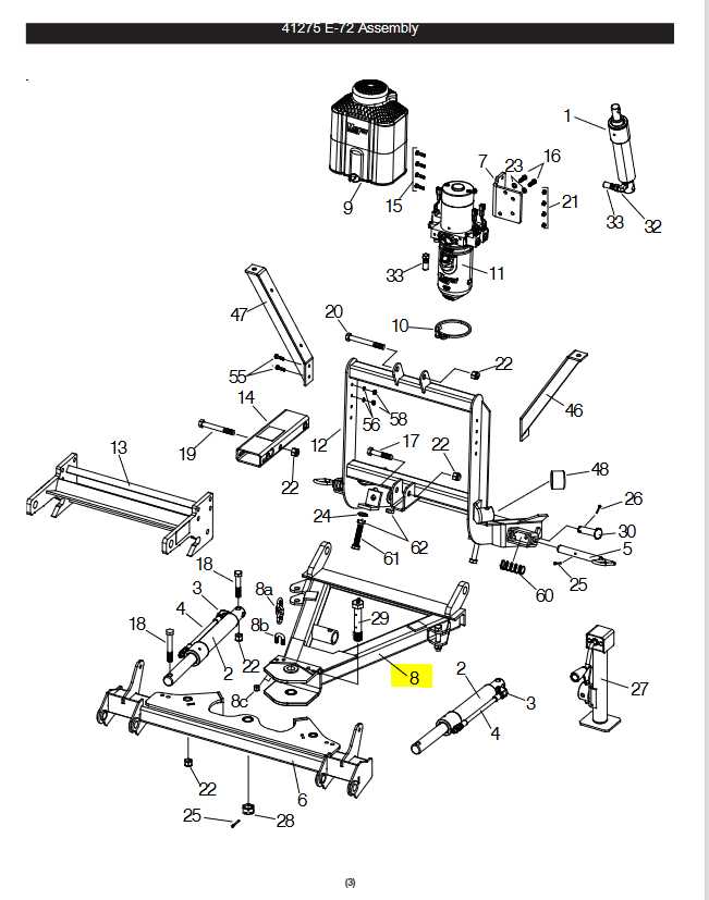
Understanding a system blueprint is essential for anyone looking to perform maintenance or repairs on a vehicle’s clearing equipment. These visual representations show how various components are arranged and connected, allowing for easy identification and troubleshooting. A proper interpretation ensures that users can make informed decisions about adjustments, repairs, or replacements.
Reading the Visual Symbols
Blueprints often use specific symbols to represent different components, such as pumps, gears, and control units. Each symbol corresponds to a particular part of the system, and understanding these symbols is the first step in interpreting the layout. Some diagrams include labels or legends to clarify the meaning of each symbol, making it easier for users to navigate through the blueprint and identify what needs attention.
Following the Flow and Connections
Blueprints also illustrate the flow of fluids or electrical connections between components. By following these lines, you can trace how power is transferred or how the system operates. This knowledge is crucial when diagnosing faults, as it helps to pinpoint areas where issues may arise, such as blockages, leaks, or malfunctioning connections. Being able to follow the flow ensures efficient troubleshooting and faster repairs.