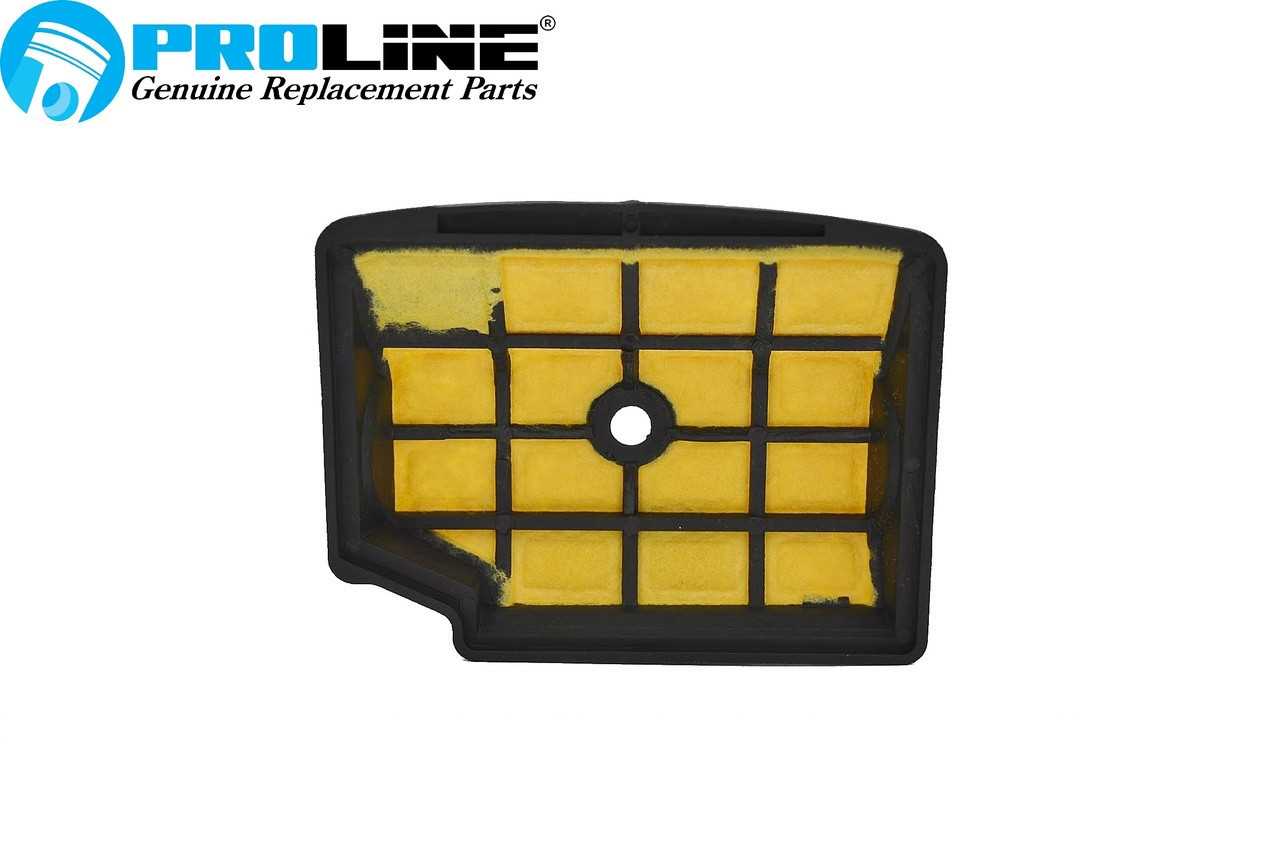
Maintaining and repairing machinery requires a clear understanding of its internal structure. A comprehensive guide to its individual elements can help users identify parts and perform effective maintenance tasks. Knowing the function and location of each component ensures efficient operation and simplifies troubleshooting.
Accurate identification of parts is essential for anyone handling equipment, as it prevents errors during repairs and maintenance. Each piece serves a specific function, and recognizing these roles is crucial for extending the lifespan of the machinery.
Efficient operation relies on familiarizing oneself with the assembly of each unit, enabling better decision-making when dealing with replacements or adjustments. Understanding the layout also aids in resolving any issues swiftly, ensuring minimal downtime and consistent performance.
Understanding the MS200T Parts Diagram
For proper maintenance and repair of any machinery, it is crucial to familiarize oneself with its internal layout and individual components. By breaking down the overall assembly into smaller sections, users can better understand how each piece contributes to the overall function. This knowledge helps in troubleshooting, maintenance, and ensuring smooth operation.
Detailed Component Overview
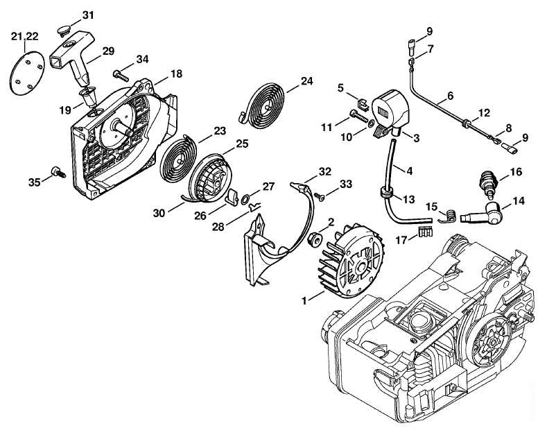
Each element in the equipment plays a significant role, whether it’s for power transmission, safety, or performance enhancement. Understanding the purpose of each part allows users to assess wear and tear, replace worn components, and make necessary adjustments to keep the unit functioning optimally. Recognizing the connections between these elements ensures that repairs are done accurately and efficiently.
Effective Troubleshooting with Visual Guides
Visual guides, such as detailed breakdowns of the unit’s structure, are invaluable for identifying issues. By referencing these guides, users can pinpoint where malfunctions occur and take the appropriate steps to correct them. This process not only saves time but also reduces the risk of further damage, ensuring the machinery remains in top condition.
Key Components of the MS200T Model
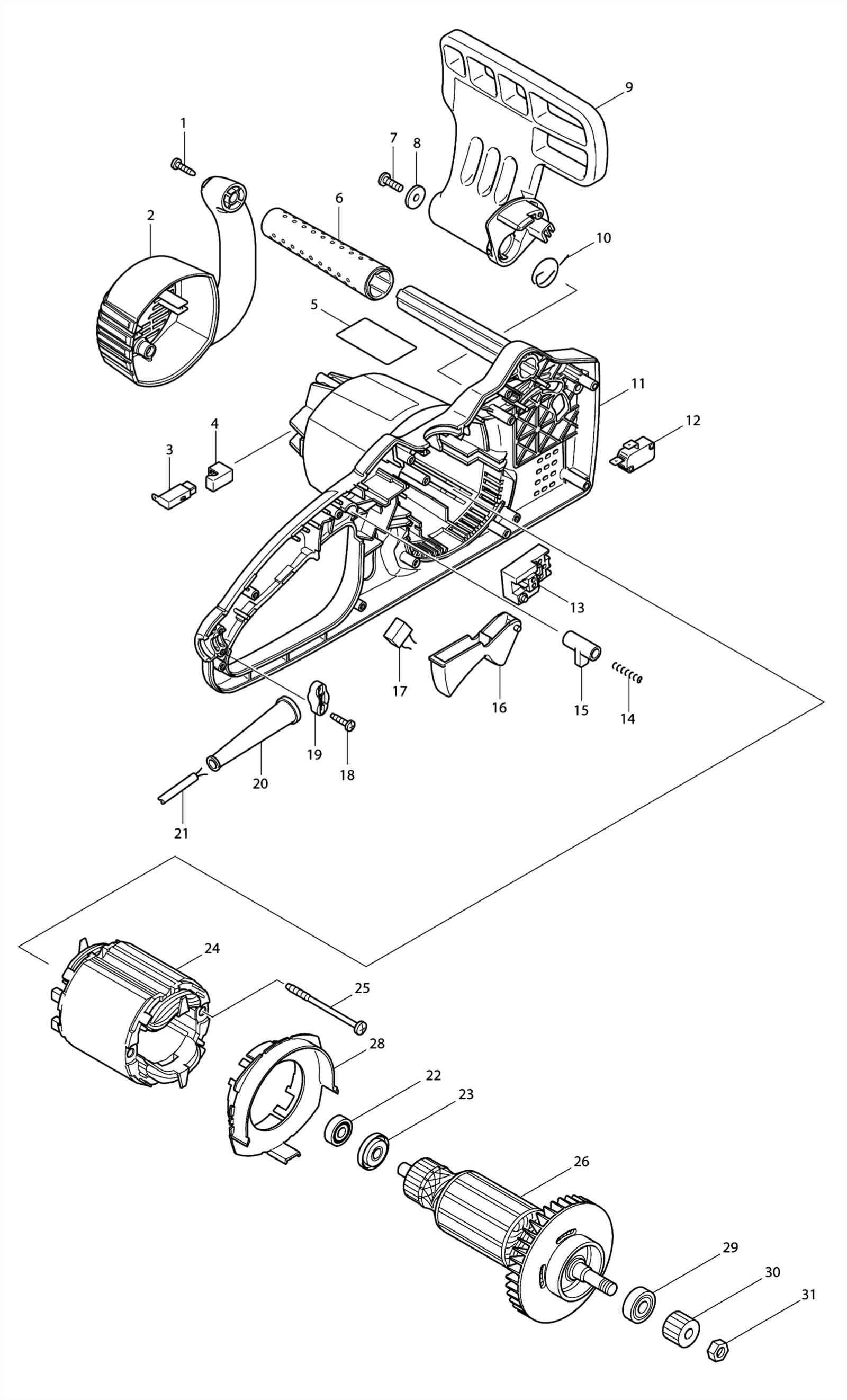
Every machine consists of a series of interconnected elements, each performing specific tasks to ensure smooth operation. Recognizing the importance of these components is essential for maintaining functionality, performing repairs, and optimizing performance. Understanding how each part contributes to the overall system allows for more efficient troubleshooting and upgrades.
Engine and Power System
The heart of any mechanical system is its engine. The engine is responsible for generating the necessary power, which is then transferred through various mechanisms to perform the intended tasks. Proper maintenance of the engine ensures reliable performance, while regular checks can prevent issues related to fuel, ignition, and compression.
Safety and Control Features
In addition to the power system, safety mechanisms play a critical role in protecting both the machine and its operator. Components like the throttle, safety switches, and other control systems allow users to manage power efficiently while ensuring safe operation. Regular inspection and testing of these features are crucial to maintaining a safe working environment.
How to Use the MS200T Parts Diagram
Understanding the layout of a machine is essential for performing repairs and maintenance efficiently. Visual guides that break down the various components allow users to quickly identify each element and its purpose within the system. By referencing these detailed representations, operators can accurately diagnose issues, replace faulty components, and assemble or disassemble parts with ease.
Step-by-Step Identification Process
Start by locating the specific section of the guide that corresponds to the area of the equipment you need to inspect or repair. Carefully study the labels and numbers next to each component to match them with the corresponding pieces on the actual machine. This methodical approach helps ensure that no part is overlooked, simplifying both repair and maintenance tasks.
Effective Troubleshooting Using Visual Cues
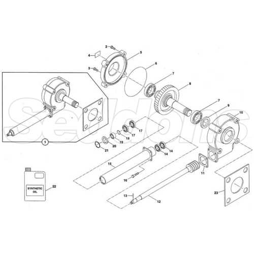
When diagnosing a malfunction, the visual layout of the machine can be an invaluable tool. By cross-referencing the malfunctioning area with the guide, users can pinpoint potential issues more quickly. Identifying worn-out or damaged components is made easier when each part’s role and location are clearly depicted, helping users to focus on the most likely causes of the problem.