Every tool has a unique set of internal and external elements that contribute to its overall functionality. Whether you’re a professional or a DIY enthusiast, it’s crucial to recognize these parts to ensure efficient maintenance and repairs. Understanding the construction and assembly of your equipment can save both time and money, preventing unnecessary service calls or replacements.
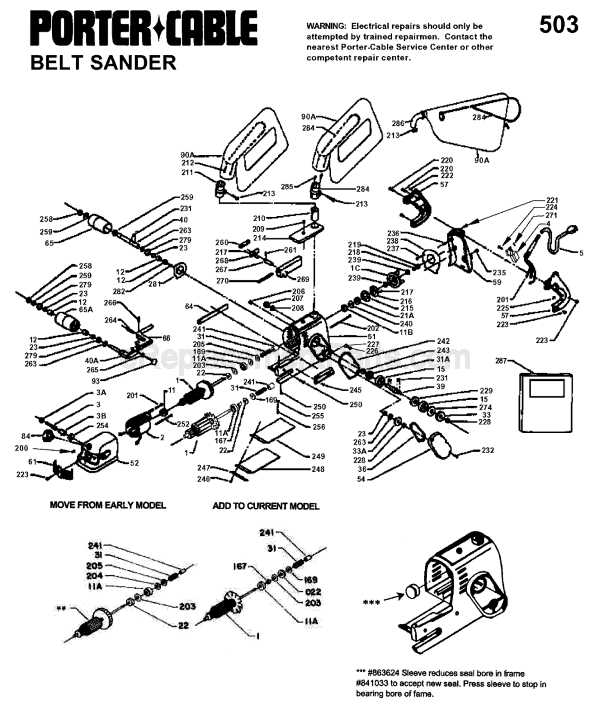
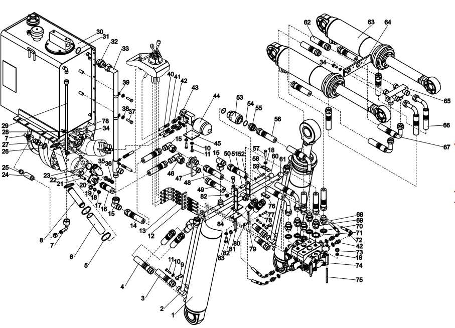
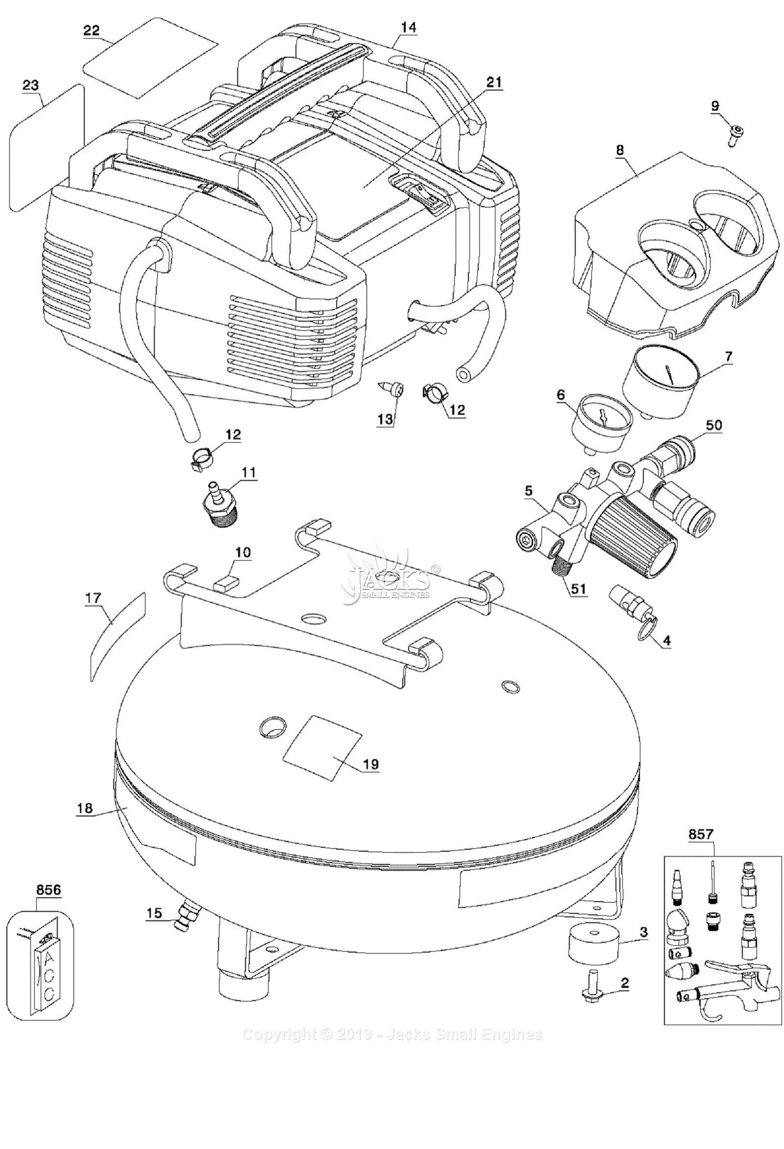
When facing issues with your equipment, referring to a detailed layout can be the key to identifying the root cause of any malfunction. These visual guides offer a clear representation of each piece and how they fit together, making repairs easier and more accurate. With a good understanding of how everything works, you’ll be well-equipped to handle common problems independently.
Knowing how to read and interpret these visual references empowers you to troubleshoot and restore tools effectively. With the right knowledge, you can maintain optimal performance, extend the lifespan of your equipment, and avoid costly replacements.
Understanding the Tool Components
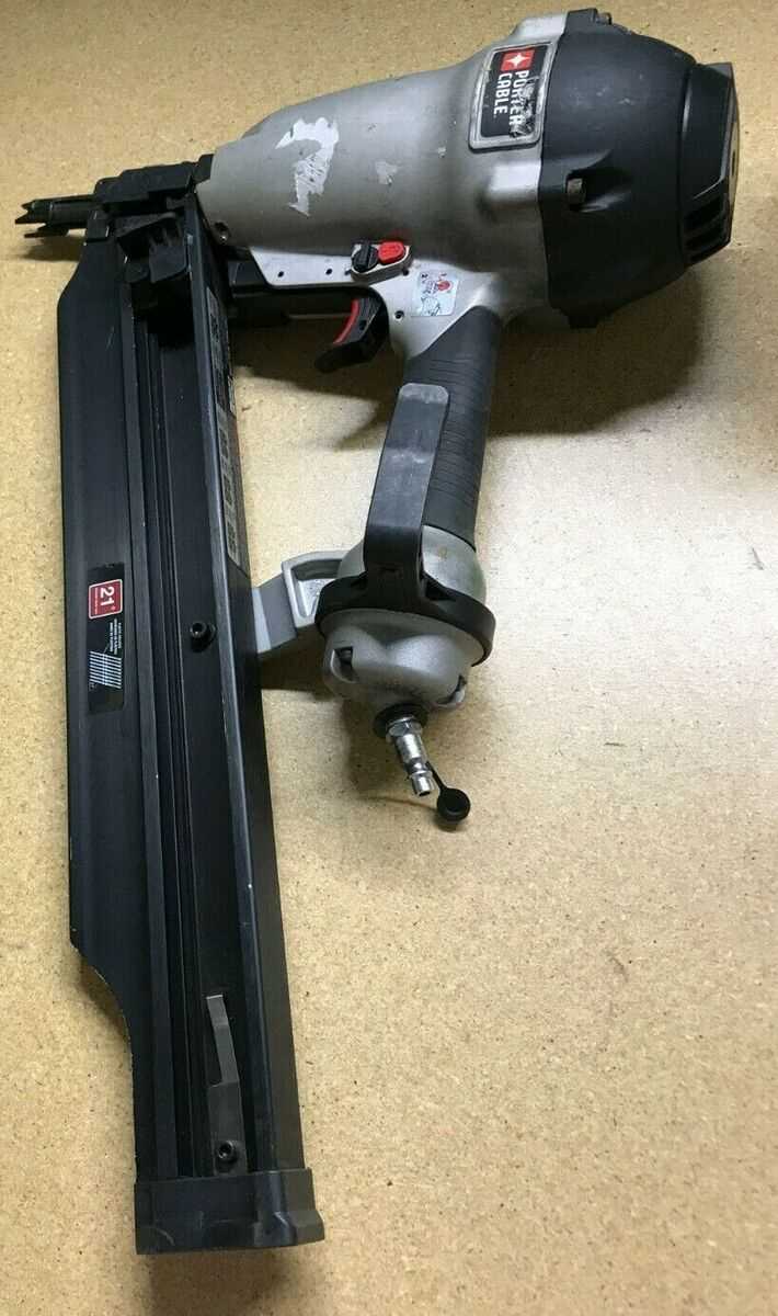
To effectively maintain and repair your equipment, it’s essential to understand the various components that make up its structure. Each element plays a specific role, and recognizing how they work together can make troubleshooting much easier. In this section, we will explore the key parts, their functions, and how they contribute to the overall performance of the tool.
Key Elements of the Tool
The core components of any mechanical device are typically designed to perform a particular task. Understanding each part’s function allows for better diagnosis when something goes wrong. Below are some of the essential elements you should familiarize yourself with:
- Trigger mechanism – Controls the activation of the tool.
- Housing – Protects internal components and provides structure.
- Motor – Powers the entire operation of the tool.
- Fasteners – Connect different parts for stability and operation.
- Safety mechanisms – Prevents accidents and ensures proper usage.
How Components Interact
Once you understand the individual elements, it’s important to recognize how they interact. The proper function of one part often relies on the precise movement or alignment of others. For example, if the trigger mechanism fails, it can prevent the motor from activating, disrupting the entire system. Knowing how these components work together is key to diagnosing issues and making repairs efficiently.
By thoroughly understanding the roles of each component, you can more easily spot problems, find replacements, and ensure that your tool continues to operate at its best.
How to Identify Key Components in the Diagram

Recognizing and understanding the components of your tool from a visual representation is essential for maintenance and repair. A detailed illustration allows you to pinpoint each element, making it easier to locate issues and select appropriate replacements. In this section, we will walk through the process of identifying the main components that are critical for the tool’s functionality.
Familiarizing Yourself with the Layout

Before diving into identification, it’s important to get comfortable with the layout of the visual guide. These layouts typically categorize parts into sections based on their role in the tool. Familiarizing yourself with the overall structure will help you quickly find what you’re looking for when you need it most.
- Sectioned Areas – These group related components together, such as the motor section or housing.
- Numbering System – Each part usually has a unique number or label for easy identification.
- Clear Labels – Many guides include part names or descriptions next to the visual representation for additional clarity.
Step-by-Step Identification Process
Once you’re familiar with the layout, you can begin identifying individual components. Follow these steps to ensure accuracy:
- Look for the labeled sections to help narrow down your search.
- Find the specific part number or label next to each component.
- Match the identified part with its function based on the visual guide’s description.
- Check for any additional annotations that may highlight specific issues or functions related to the part.
By following these steps, you’ll be able to quickly and accurately identify the parts you need, simplifying repairs or replacements significantly.
Repair Tips Using the FR350 Parts Diagram
When it comes to fixing a malfunctioning tool, a visual guide can be a valuable resource. It helps you identify which components are worn or damaged, making the repair process more straightforward. By following these tips, you can effectively use the visual representation to carry out repairs with greater precision and confidence.
Step-by-Step Repair Process
Understanding the tool’s layout is the first step to making any repair. Once you know where the key components are located, you can focus on the areas that need attention. Below are some tips to guide you through the repair process:
- Identify the Problem Area – Look for any components that appear damaged, broken, or out of place in the illustration.
- Check for Wear and Tear – Over time, some parts may wear down. The diagram will help you identify parts that typically experience the most stress and need replacement.
- Consult the Labels – The visual guide often includes detailed labels that indicate the part number and sometimes even troubleshooting tips.
- Work Methodically – Follow the layout to disassemble and reassemble parts carefully, ensuring that each component is in place before moving to the next step.
Tools and Replacement Parts

For a successful repair, you’ll need the right tools and replacement components. The diagram can help you identify the necessary parts, and by cross-referencing with the manufacturer’s manual or a trusted supplier, you can ensure you have the correct items before starting the repair.
By using these tips in conjunction with the visual guide, you can make your repairs more efficient and effective, prolonging the life of your tool.