Understanding the structure and components of any heavy-duty equipment is essential for proper upkeep. Whether you’re a professional or a DIY enthusiast, knowing the different elements and their functions can significantly improve the tool’s longevity and performance.
Accurate identification of each individual part is the first step in efficient maintenance and troubleshooting. With clear visual references, you’ll be able to spot issues early and handle replacements or repairs with ease.
By examining the layout of your equipment, you can gain valuable insights into its inner workings. This guide will help you navigate through the most common problems and offer tips for maintaining the tool in peak working condition.
Understanding Ridgid 700 Parts Layout

Properly understanding the internal configuration of any tool is crucial for effective maintenance. Each component serves a unique function, and a clear overview helps in quickly identifying any potential issues. Recognizing how these elements are organized ensures easier access when replacements or repairs are needed.
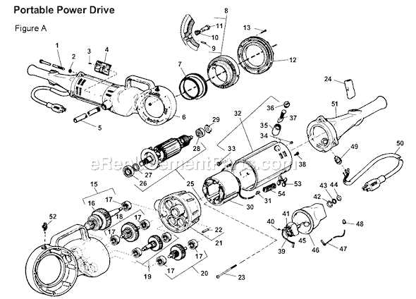
The layout provides a structured view of all the key parts, allowing users to pinpoint specific areas that require attention. From motor assembly to auxiliary elements, each section is designed to work seamlessly with others, contributing to the tool’s overall efficiency and durability.
Having a clear understanding of how the parts are arranged also aids in troubleshooting. If a malfunction occurs, knowing where to look first can save time and effort. A well-organized visual reference is an invaluable tool for anyone seeking to maintain or repair their equipment.
How to Use Ridgid 700 Parts Diagram
Using a visual guide to understand the layout of tool components is essential for successful repairs and maintenance. Such references provide a detailed illustration of each element, helping users identify and address issues more effectively. By following this guide, you can quickly locate the specific part that requires attention or replacement.
To make the most of these illustrations, start by locating the section corresponding to the part you’re interested in. Once identified, check for any markings, numbers, or labels that will direct you to the right replacement component or offer troubleshooting advice. Each visual reference is designed to help you work systematically through the tool’s inner workings.
By familiarizing yourself with the layout and components, you’ll be better equipped to make informed decisions about maintenance. This method not only saves time but also ensures that your equipment continues to function efficiently, reducing the risk of further damage or wear.
Common Issues with Ridgid 700 Parts

Many mechanical tools face recurring problems related to their internal components. Over time, wear and tear can cause specific issues that impact performance, safety, and efficiency. Being aware of the most frequent malfunctions can help in preventing costly repairs and prolonged downtime.
One of the most common issues is improper lubrication, which leads to overheating and component failure. Another issue often encountered is the misalignment of moving parts, causing uneven wear or damage. Additionally, damaged seals or connections can lead to leaks or loss of power, which disrupts the tool’s operation.
Understanding these typical problems allows users to address them early. Regular inspection and timely replacement of faulty components ensure that the tool remains in optimal working condition and continues to operate efficiently over time.