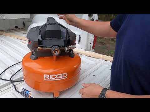
Having a clear understanding of your machinery’s internal components is essential for proper maintenance and troubleshooting. Knowing how each element fits together allows for better care and enhances the overall longevity of the system. Identifying specific parts and understanding their function helps you make informed decisions when repairs are needed.
In this guide, we will explore how to interpret the layout of various mechanical systems. You will learn how to locate different parts and understand their roles within the whole structure. With this knowledge, you’ll be more confident in diagnosing issues and performing repairs or replacements.
Whether you’re a seasoned technician or a first-time user, understanding these essential details is key to maintaining efficiency. Regular inspections and a solid grasp of your equipment’s construction can prevent costly mistakes and ensure smooth operation for years to come.
Understanding Equipment Components

Every mechanical system consists of various elements that work together to ensure proper functionality. Each component plays a specific role, from generating power to regulating flow, and understanding how they interact is crucial for effective maintenance. By recognizing the purpose and placement of each part, operators can more easily identify potential issues and address them promptly.
Key Elements of the System
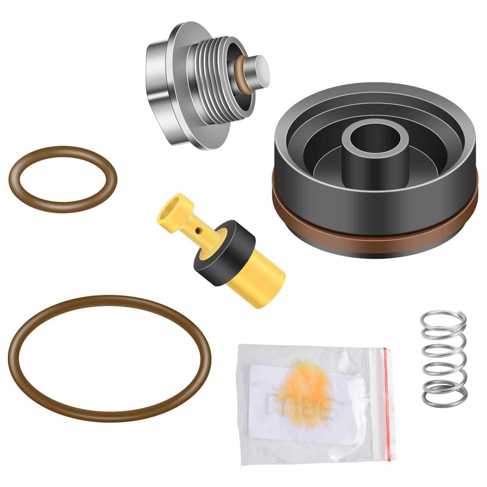
The core structure of any mechanical unit includes components like valves, pistons, and motors, which are responsible for different functions within the machine. These elements must be in good condition for optimal performance. For example, the motor drives the operation, while valves control pressure and airflow. Understanding these key parts will allow for more efficient troubleshooting and repair.
How to Identify and Maintain Components
Knowing where each part is located and how it contributes to the system’s overall operation is essential for regular upkeep. Regular checks on high-wear items, such as filters or seals, are important to prevent breakdowns. Detailed manuals or reference guides can help identify specific components, making the maintenance process smoother and more effective.
How to Read Equipment Layouts
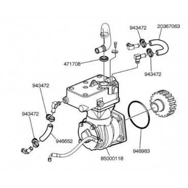
Understanding the layout of a mechanical system is essential for troubleshooting and repairs. These visual guides offer a clear representation of how different elements are connected, making it easier to identify where issues may arise. Interpreting these representations requires knowing how to read symbols and follow the flow of energy and materials throughout the system.
Start with the Legend – Most reference guides include a legend or key to explain the symbols used in the layout. These symbols represent various parts, such as valves, pistons, and motors. Familiarizing yourself with these symbols is the first step in reading the schematic correctly. Once you know what each symbol represents, you can follow the lines to understand how each part connects to the others.
Follow the Flow – After recognizing the components, it’s important to follow the flow lines that show how the system operates. These lines often represent air, liquid, or electrical current, and understanding their path will help you identify which parts are critical to the overall function. By studying the flow, you can pinpoint potential blockages or failures in the system.
Common Issues and Part Replacements for Compressing Systems
Even the most reliable mechanical systems experience wear and tear over time. Understanding common issues and knowing which components may need replacing can significantly extend the life of your equipment. Regular maintenance and early detection of problems can help prevent costly repairs and downtime.
Frequent Problems in Mechanical Systems
Common issues that arise in these machines often include reduced efficiency, pressure inconsistencies, or even complete system failure. Worn seals, clogged filters, or damaged motors are frequently the culprits behind these problems. Identifying these symptoms early can prevent further damage and ensure the system continues to function smoothly.
Replacing Worn or Faulty Components

When components like valves, filters, or pressure switches begin to malfunction, replacing them promptly is essential. These parts are often designed for easy removal and installation, allowing for quick fixes without the need for professional assistance. Always refer to a detailed manual to identify the correct replacement parts and ensure proper installation.