When it comes to maintaining machinery, having a clear overview of its internal structure is crucial for efficient operation and repair. A well-structured guide showing the individual elements allows for quicker troubleshooting and precise assembly. Knowing how each part contributes to the overall system helps in identifying and addressing any issues that may arise.
Detailed visuals of the components are essential for understanding the connections and functions of each element. These visuals offer a comprehensive look at how the various parts interact with each other, ensuring smooth and effective performance. By familiarizing yourself with these layouts, you can optimize maintenance and repairs with confidence.
Proper identification of each section within the system is key to reducing downtime and improving the longevity of the equipment. A visual guide provides an invaluable resource, assisting users in making informed decisions about repairs and replacements when needed.
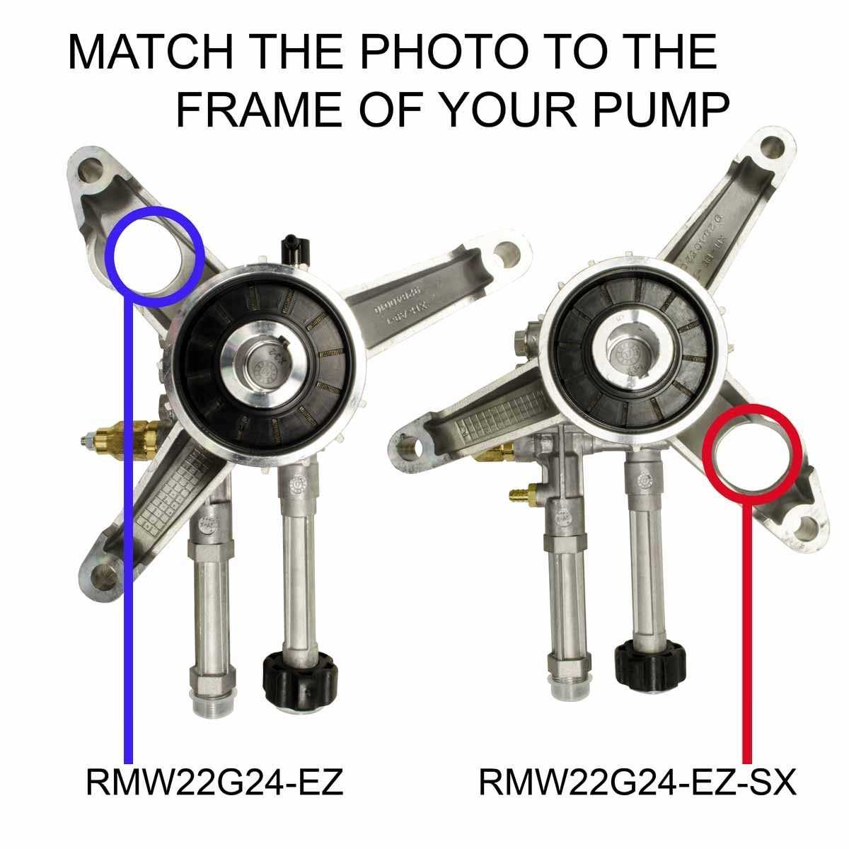
Understanding the Rmw 2.2 G24 Parts
To ensure the longevity and proper functioning of any machinery, it is essential to comprehend the role of each individual component. These elements work together to deliver optimal performance, and knowing their specific functions helps in diagnosing issues and facilitating repairs. Whether it’s a mechanical or a more intricate system, understanding the layout and interaction between parts is fundamental for efficient maintenance.
Key Functional Elements
The internal components are designed with specific purposes in mind, ensuring the system operates smoothly. Each element is interconnected with others, creating a seamless workflow that powers the entire machine. Understanding how each part contributes to the larger mechanism is vital for troubleshooting and ensuring that no part is neglected during maintenance.
Maintenance and Troubleshooting Tips

Familiarizing yourself with the core components also enhances your ability to handle repairs and avoid potential damage. Knowing where each part fits and how it interacts with other elements can significantly reduce downtime. By maintaining a close understanding of these features, users can prevent issues before they escalate, ensuring the machinery continues to operate at peak efficiency.
Key Components and Their Functions

Every machine consists of numerous elements, each designed to perform a specific function to ensure the system runs effectively. Understanding the role of each component helps users maintain and repair the equipment, ensuring that all parts are functioning optimally. From the smallest connectors to the most complex systems, each part plays a critical role in the overall operation.
Core System Elements
The core components are responsible for powering and controlling the machine. These elements interact with one another to ensure the smooth flow of energy and functionality. For example, the main drive components provide the necessary force, while auxiliary parts support and enhance the performance of the entire system.
Supportive and Auxiliary Components

In addition to the primary elements, supportive components play a vital role in maintaining operational efficiency. These parts help with regulating temperatures, managing pressure, and ensuring safety. Regular maintenance of these auxiliary parts ensures that the core system operates without disruption, contributing to the machine’s overall reliability and performance.
How to Use the Parts Diagram
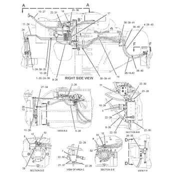
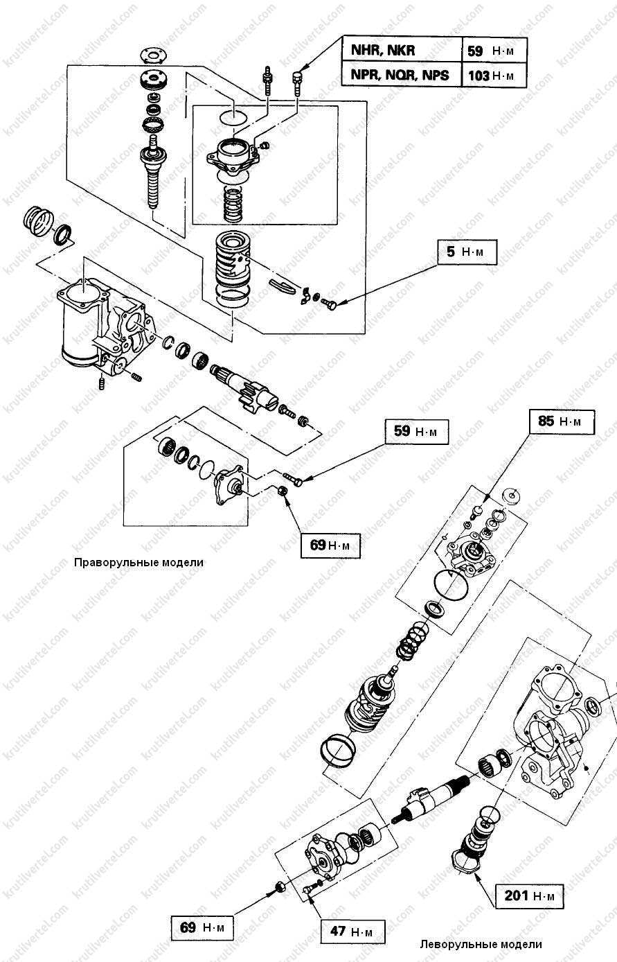
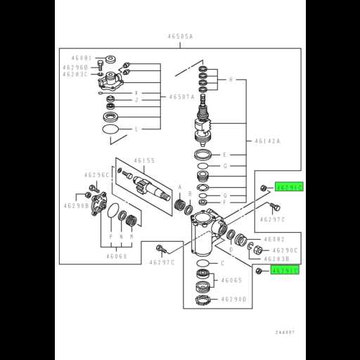
A visual representation of a machine’s internal components is an invaluable tool for anyone looking to maintain or repair the system. It provides a detailed layout that highlights the placement and function of each element, making it easier to identify issues and locate parts that need attention. By learning how to interpret these visual guides, you can significantly improve your ability to troubleshoot and ensure proper maintenance.
Step-by-step approach is crucial when using these guides. Begin by familiarizing yourself with the overall structure, focusing on the main sections. From there, use the visual representation to locate specific parts and understand how they interact with other elements within the system. This helps in pinpointing potential issues more efficiently.
In-depth understanding of each component’s position and function allows for more accurate repairs. Once you identify a faulty or worn-out part, referencing the guide ensures that you are replacing the correct piece, reducing the risk of errors during maintenance. This methodical approach helps to keep your equipment running smoothly for a longer period.