Understanding the intricate design of a multifunctional workshop tool is essential for effective use and maintenance. The ability to identify and comprehend each element of the machine can significantly enhance its performance and longevity. A visual reference of the tool’s internal structure allows users to pinpoint individual components with ease, facilitating repairs and upgrades.
Proper knowledge of each part not only aids in smooth operation but also ensures safety and efficiency. Whether you’re a seasoned professional or a beginner, familiarizing yourself with the key elements can prevent potential issues and streamline your workflow. By learning how to interpret detailed visual layouts, users can confidently handle maintenance tasks.
In the following sections, we will explore the essential features of the machine, guiding you through the different components and their roles. This practical insight will help you manage your equipment more effectively, allowing for smoother operation and fewer disruptions in your tasks.
Understanding the Shopsmith Mark V Diagram

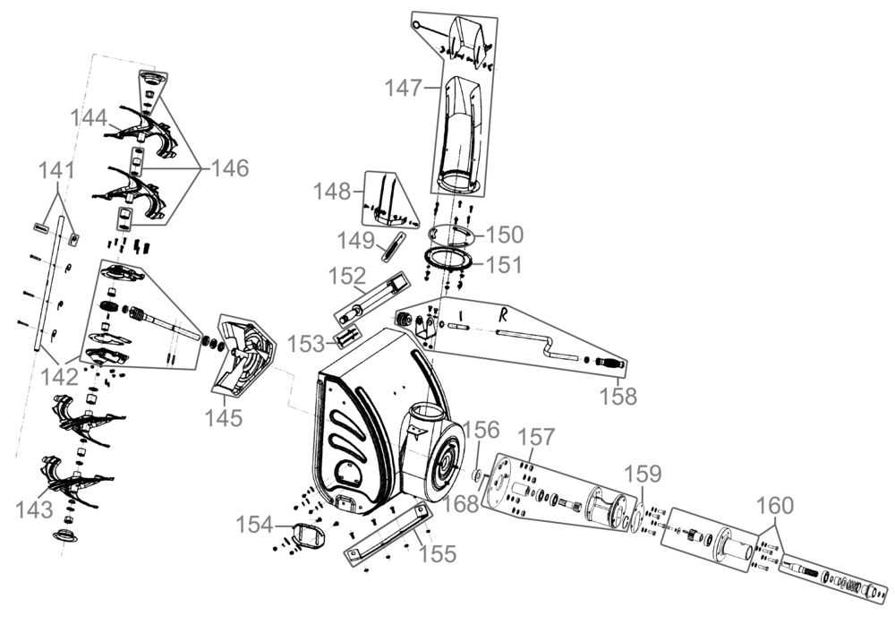
A detailed visual representation of a machine’s components provides valuable insight into its construction and functionality. These layouts are essential for identifying the various elements that make up the tool, making it easier to understand how each part interacts with the others. By analyzing this type of illustration, users can grasp the underlying structure of the equipment, ensuring smoother operation and maintenance.
How to Read the Visual Representation

Each section of the image is typically labeled to correspond with specific components, making it simpler to identify individual pieces and understand their purpose. Familiarity with this format helps users quickly find the parts they need to inspect, replace, or adjust, minimizing downtime and maximizing efficiency during repairs. Paying attention to small details such as connections and orientation ensures the tool remains in optimal condition.
Benefits of Using a Component Layout
Using a visual guide not only simplifies troubleshooting but also aids in organizing maintenance tasks. Whether you’re assembling, disassembling, or upgrading, having a clear reference of how everything fits together reduces the likelihood of errors. Additionally, it allows for more precise repairs, extending the lifespan of the tool and improving its performance.
Identifying Key Components of the Machine

Understanding the primary elements of any equipment is essential for effective operation and maintenance. By recognizing the key components, users can ensure the machine functions smoothly and efficiently. This knowledge allows for easier identification of potential issues, making it possible to address problems before they cause significant disruptions.
Each machine consists of several critical parts that work together to perform a variety of tasks. These components often include motors, drive mechanisms, and supporting structures, all of which play a vital role in the overall performance. Familiarizing yourself with these elements helps in troubleshooting and conducting routine maintenance, ensuring that each part is in working order.
Recognizing the correct arrangement and interaction between these elements will also guide you through the process of repairs or upgrades. A comprehensive understanding of the system enables you to handle issues more effectively, preventing unnecessary damage and reducing downtime.
How to Use the Parts Diagram for Repairs
When tackling repairs on a complex machine, having a clear visual guide is invaluable. A well-organized illustration of the system’s components allows you to identify the exact location of each part, making it easier to locate the source of the issue. By referencing this type of visual aid, you can efficiently plan and execute repairs without missing critical steps.
Step-by-step repair processes become much simpler when each piece is clearly marked. This guide will help you pinpoint which components need attention and how to approach their replacement or adjustment. Whether you are fixing a worn-out piece or addressing a malfunction, this tool ensures that you follow the correct sequence, reducing the risk of errors.
By following the visual representation closely, you can avoid unnecessary disassembly or confusion. This method also allows you to keep track of small parts, ensuring they are properly installed and aligned. With this approach, repairs can be completed more efficiently, minimizing downtime and extending the life of your equipment.