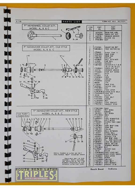
Understanding the intricate components of any mechanical system is crucial for both maintenance and repair. Identifying each element and knowing its function can greatly enhance your ability to operate the machinery effectively and troubleshoot any issues that arise. This knowledge also contributes to improving the overall performance and longevity of the equipment.
In this guide, we will focus on a well-known model, exploring its key elements and how they fit together within the larger assembly. By breaking down each section, you’ll gain insight into the mechanics that allow the machine to function smoothly, making it easier to address any problems or perform upgrades when needed.
Whether you are a seasoned professional or a newcomer, learning to identify and understand the components of these machines is a valuable skill. With this comprehensive overview, you’ll be better prepared to maintain and optimize your equipment, ensuring reliable operation for years to come.
Understanding the South Bend 9 Lathe Components
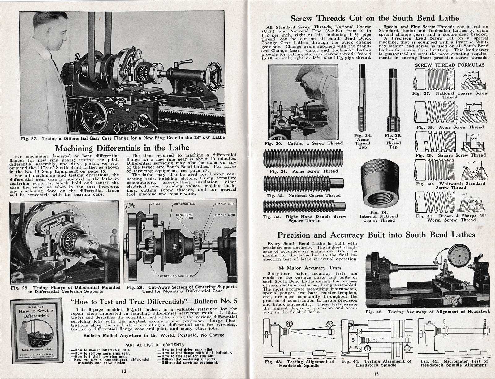
Every machine is made up of multiple interconnected elements, each with a specific function that contributes to the overall operation. In order to maximize efficiency and troubleshoot problems effectively, it’s important to have a clear understanding of these key components and how they interact. By familiarizing yourself with the various parts, you can ensure smooth operation and perform necessary repairs with ease.
This machine consists of several major sections, including the drive mechanism, tool holding assembly, and motion control elements. Each of these sections plays a crucial role in the performance of the system, whether it’s cutting, shaping, or handling material. Understanding these components helps operators recognize potential issues and address them promptly to maintain optimal functionality.
As you delve into the specifics of each element, it becomes clear how the design of this system prioritizes precision and durability. Knowing the function and location of every part not only makes maintenance tasks more efficient but also empowers you to modify or upgrade your equipment as needed to meet specific demands.
Key Parts of the South Bend 9 Lathe Explained
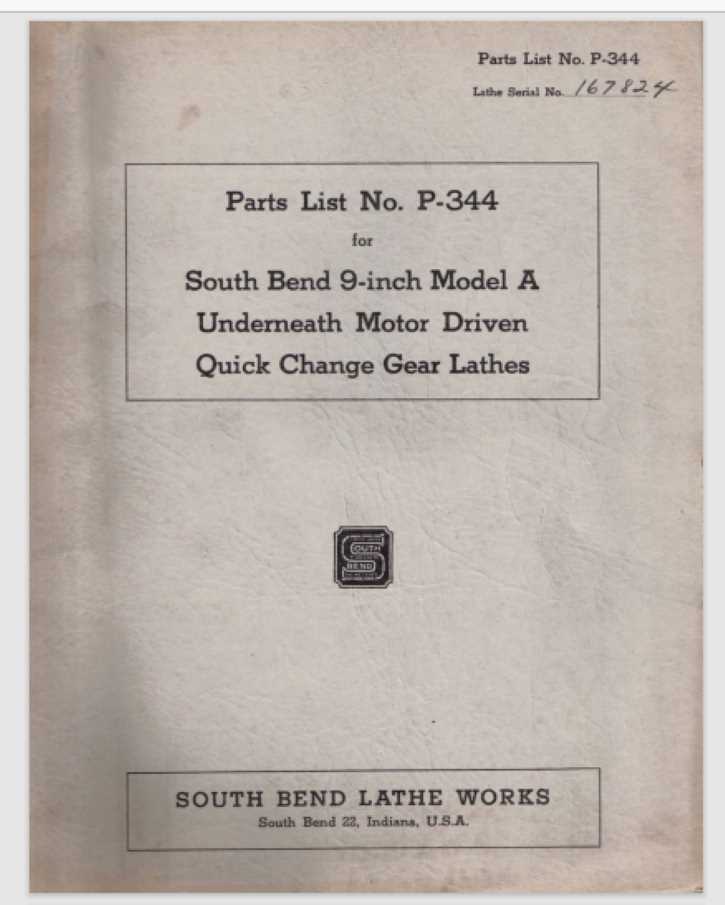
Understanding the individual components of any machinery is essential for proper operation and maintenance. Each part serves a specific function, and when they work in unison, they enable the system to perform with precision. In this section, we will break down the primary elements of the system, focusing on their roles and how they contribute to the machine’s overall functionality.
The main drive unit is the core of the mechanism, providing the necessary power to initiate motion. This unit typically includes a motor and a series of belts or gears that transfer energy to other components. The carriage assembly, which holds the tool and moves it along the workpiece, is another critical part. It ensures accurate cuts and helps maintain consistency during operations.
In addition to these, the tailstock plays a pivotal role in supporting longer workpieces, providing stability during the cutting process. The bed serves as the foundation, aligning all parts and ensuring that everything remains in proper position. Lastly, the control mechanisms allow the operator to adjust settings for speed, feed, and depth of cut, ensuring the system runs smoothly and meets the necessary specifications.
How to Read a South Bend 9 Lathe Diagram
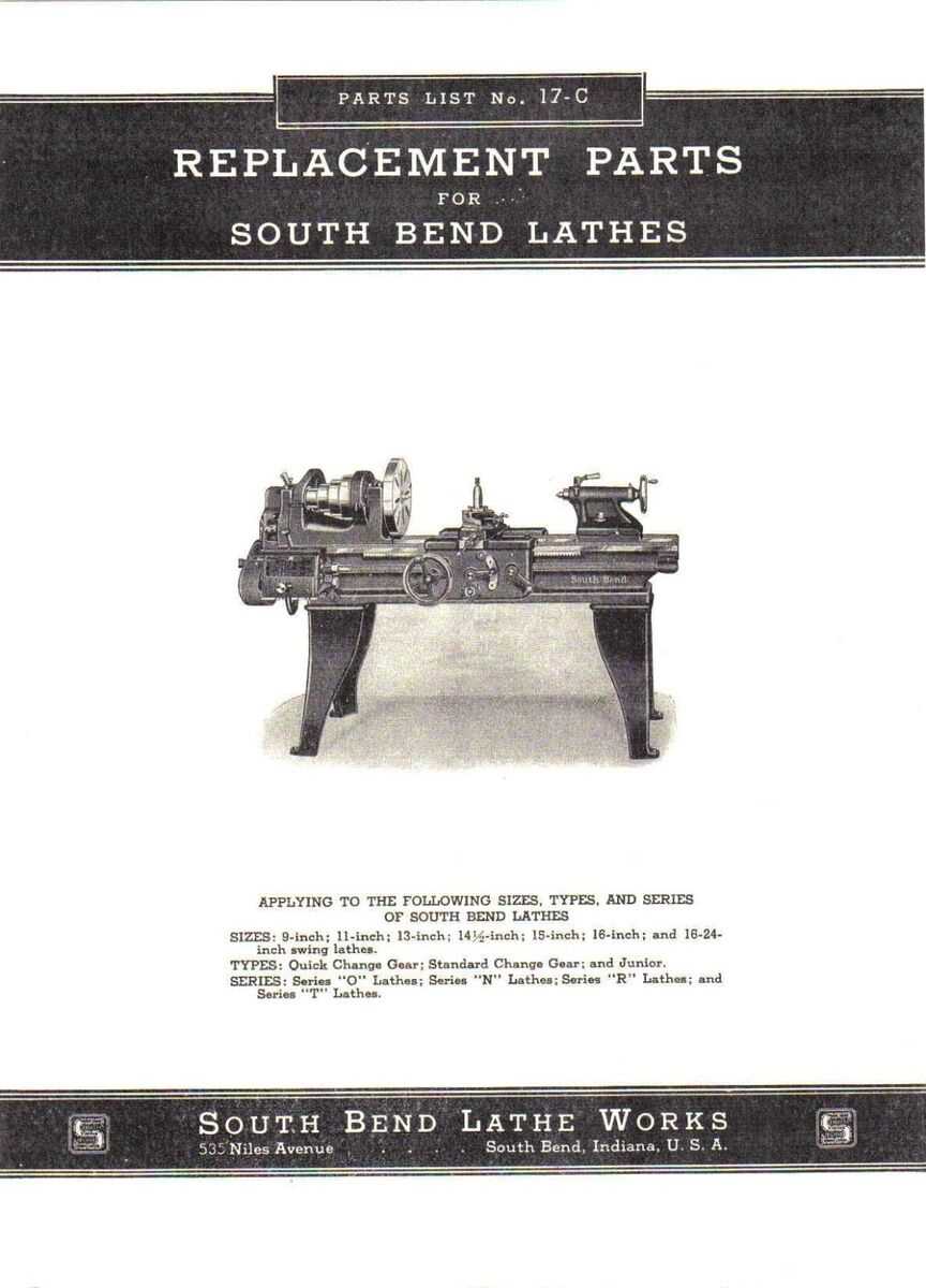
Interpreting a mechanical schematic is an essential skill for understanding the arrangement and function of various components in a system. A well-designed illustration provides a visual representation of the machine’s structure, allowing you to identify individual parts and their relationships to one another. By learning how to read these illustrations, you gain a deeper understanding of the machinery and can effectively troubleshoot or make adjustments.
Familiarizing Yourself with the Layout
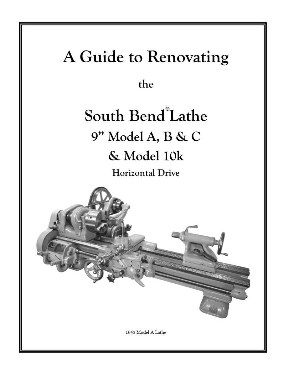
Before diving into the specifics, it’s important to familiarize yourself with the overall layout of the schematic. Each section of the drawing typically corresponds to a major part of the machine, such as the drive system, tool holder, or support mechanisms. These sections are usually represented by clear, labeled symbols or shapes that indicate their position and connection within the system.
Understanding the Labels and Symbols
One of the key elements in reading a schematic is understanding the labels and symbols used to represent different components. These symbols are standardized and provide information such as size, shape, and function. By following the key or legend, you can interpret these symbols accurately and gain insight into the machine’s operation. This skill is particularly useful for identifying wear points or areas that may require maintenance.