Maintaining and repairing complex machinery requires a clear understanding of its individual elements. By knowing how each part functions, you can ensure smoother operation and avoid costly breakdowns. Proper identification of these components is crucial for anyone working with heavy equipment.
In this guide, we will dive into the crucial components of a stump grinding machine, explaining their role and how they work together. Whether you are a professional or a beginner, understanding the layout and functionality of these parts will make the maintenance process much more straightforward.
Understanding the layout is the first step toward efficient repairs. Once familiar with the structure of the machine, you’ll be able to identify issues more quickly and accurately, ensuring that your equipment operates at peak performance. This knowledge also aids in selecting the correct replacement parts, reducing downtime and increasing productivity.
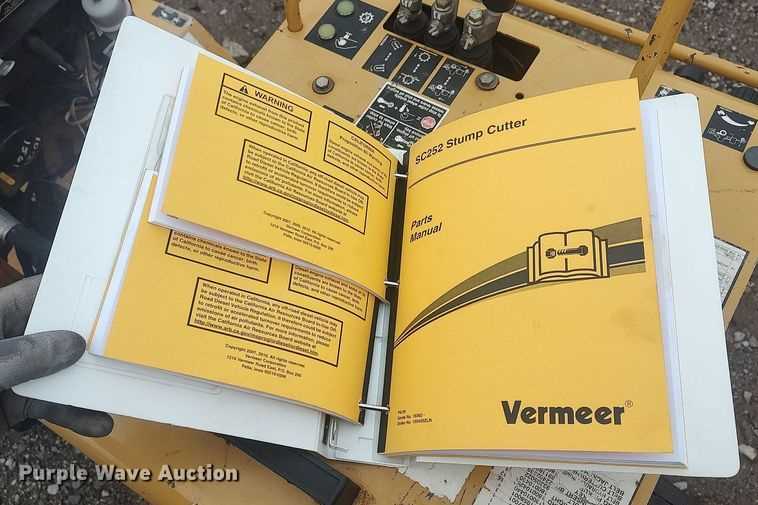
Understanding Vermeer SC252 Components
To efficiently operate and maintain a stump grinding machine, it’s essential to have a solid understanding of its key components. Each part plays a significant role in the overall performance, and knowing their functions allows for quicker troubleshooting and more effective repairs. The right knowledge will also guide the replacement of worn-out elements, ensuring the machine stays in top condition for long periods.
Core Elements of the Grinder

The core structure of a grinding machine includes components that directly affect its cutting ability, mobility, and safety. Key elements include the engine, grinding wheel, and hydraulic system. These essential parts are interconnected, and any malfunction can cause performance issues or even lead to breakdowns.
Support and Safety Features
In addition to the core working components, machines like these have numerous support elements that contribute to their stability and user safety. Components such as the frame, control systems, and safety shields help protect the operator while enhancing machine durability. Understanding these features is crucial for proper operation and ensuring that the equipment is safe to use in various environments.
Key Parts of the SC252 Stump Grinder

Every stump grinding machine consists of critical elements that ensure its effective operation. These components work together to perform the task of grinding stumps efficiently, allowing the equipment to tackle tough outdoor jobs with ease. Understanding the function of each major part helps with both routine maintenance and emergency repairs.
Engine and Power System form the backbone of any grinding machine. The engine powers the entire operation, providing the necessary force for the grinding wheel to rotate at high speeds. A properly maintained engine is crucial for optimal performance and avoiding interruptions during operation.
Grinding Wheel is the primary tool responsible for the actual stump removal. Equipped with heavy-duty teeth, it grinds through wood and roots, ensuring the stump is reduced to manageable pieces. Regular checks on the condition of the wheel and teeth will prevent inefficiencies and ensure smoother work cycles.
Hydraulic System controls the movement of the grinding head and the machine’s mobility. It is essential for adjusting the height and angle of the wheel, as well as moving the machine into position. A well-maintained hydraulic system ensures consistent performance and allows for smooth operation during use.
How to Read the Vermeer SC252 Diagram

Understanding technical illustrations is an essential skill when working with heavy equipment. These visual representations are designed to help you identify individual components, their arrangement, and how they interact within the system. By becoming familiar with how to interpret these diagrams, you can streamline repairs, identify worn parts, and make informed decisions during maintenance.
Breaking Down the Symbols
Most technical drawings use specific symbols and notations to represent various components and connections. It’s important to learn the meaning behind each symbol to understand the layout. For example, different lines might indicate electrical wiring, fluid pathways, or structural elements. Recognizing these symbols will make the entire diagram much easier to navigate.
Following the Flow and Connections
Another crucial aspect of reading these diagrams is understanding the flow of energy, whether it’s hydraulic, electrical, or mechanical. Follow the lines carefully to see how each part is powered or connected. This knowledge helps diagnose issues such as power failures or fluid leaks, allowing for quicker troubleshooting and effective repairs.