Maintaining and repairing a vessel’s navigation system requires a solid understanding of its individual components and how they interact. Knowing how to identify and troubleshoot the main elements of the control mechanism can ensure smoother handling and extend the lifespan of your equipment.
Every vessel relies on a combination of mechanical and hydraulic parts to transmit force from the wheel to the rudder. Whether you are a DIY enthusiast or a professional, being able to read and interpret the layout of these components is essential for efficient repairs and replacements.
Recognizing the different elements of the system can significantly improve your ability to pinpoint issues. Familiarizing yourself with how each part works and connects will make maintenance tasks much easier. In this guide, we will break down key aspects of these systems and explore ways to approach any repairs.
Understanding Marine Control System Components
At the heart of every vessel’s maneuvering mechanism is a series of interconnected elements that work together to control direction and responsiveness. These components, although varied in function and design, form a cohesive system that ensures smooth and precise operation.
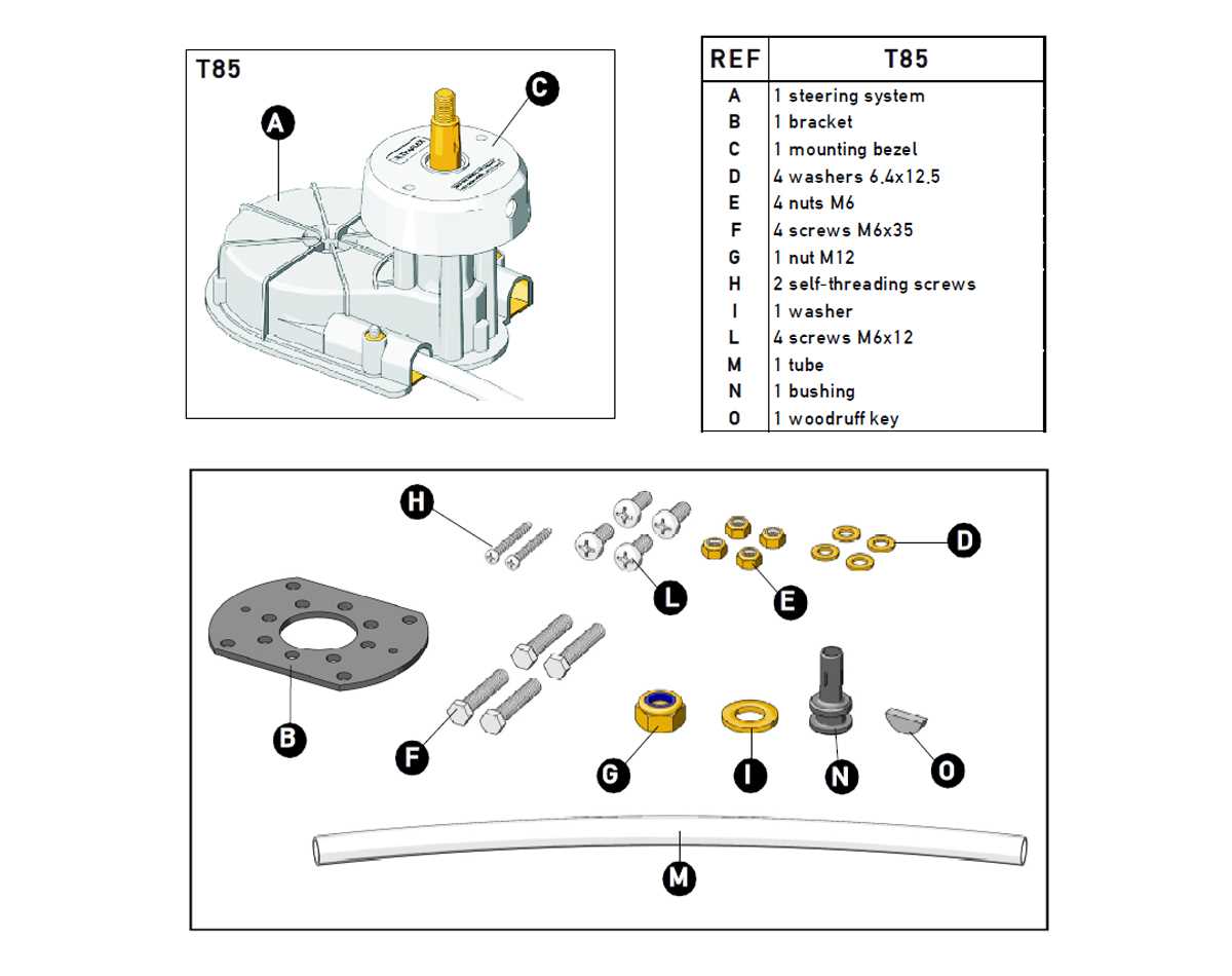
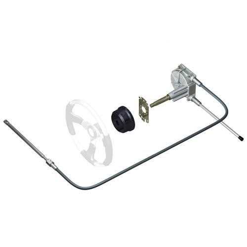
The main elements of this system include the transmission unit, which transfers motion, the hydraulic or mechanical linkages, and the wheel or lever that initiates movement. Understanding the role of each part in this network is crucial for effective operation and troubleshooting.
When inspecting or maintaining these components, it’s important to know how they communicate with each other. For example, the cables or hydraulic lines provide the necessary force for movement, while the helm mechanism translates the user’s input into directional changes. Each piece has a unique purpose but relies on the others for optimal performance.
How to Read Marine Control System Layouts

Understanding how to interpret a layout of your vessel’s navigation system is essential for maintenance and troubleshooting. These layouts represent the interconnection of various components and help identify their function within the system.
The key to reading these layouts effectively lies in recognizing the symbols and lines that represent different parts. Typically, a layout will show each element’s placement, how they are linked, and the flow of power or motion between them. Pay close attention to the markings that indicate specific directions, connections, or functions.
To make sense of a layout, begin by identifying the main control unit and trace how it communicates with other components, such as cables or hydraulic lines. Understanding these relationships will help you diagnose issues and make informed decisions during repairs.
Common Issues with Marine Control System Components
Like any mechanical system, the navigation mechanism of a vessel can experience a variety of issues that affect its performance. These problems can range from minor inconveniences to more severe failures, often due to wear and tear, incorrect installation, or lack of maintenance.
Wear and Tear on Cables and Linkages
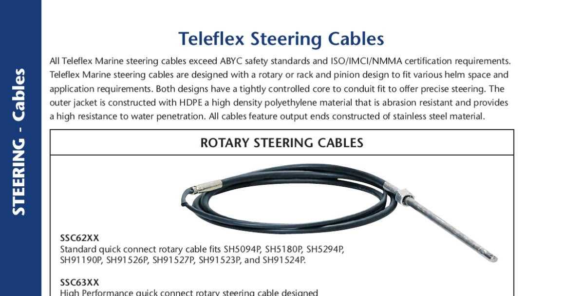
One of the most common problems in the system is the degradation of cables and linkages over time. Continuous use can cause these components to stretch, fray, or become damaged, leading to poor responsiveness or difficulty in turning. Regular inspections can help spot early signs of wear, allowing for timely replacements and minimizing operational disruptions.
Hydraulic Fluid Leaks

Hydraulic systems are highly susceptible to leaks, which can result in loss of pressure and diminished performance. These leaks often occur at fittings, hoses, or seals, and may be difficult to detect without close inspection. If left unchecked, hydraulic fluid leaks can lead to complete system failure, making early detection crucial for safe operation.