When maintaining or repairing your outdoor equipment, it’s crucial to have a clear understanding of its individual elements and their functions. Each component plays an essential role in the overall performance and efficiency of the machine. This guide will help you identify and understand the key components needed for upkeep and repairs.
By familiarizing yourself with the various pieces of the device, you can ensure proper assembly and troubleshooting. Whether you’re replacing a broken piece or performing regular maintenance, knowing the structure of your tool is vital for its longevity and smooth operation.
Accurate identification of each part allows for precise replacements, improving the efficiency of the work process. With a well-organized overview, you can confidently handle any adjustments or repairs your equipment might require. This will also save time and effort in finding the right parts when needed.
Understanding FS 55 R Components
Each tool is made up of various elements that work together to ensure its functionality and durability. Recognizing the specific roles of these components is essential for maintaining the machine and troubleshooting any issues. In this section, we will explore the main sections of the device and their contributions to overall performance.
Major Elements of the Tool
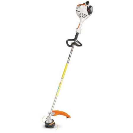
The key components of the equipment include the motor, drive shaft, cutting head, and fuel system. Each of these parts plays a critical role in how the tool operates, from powering the mechanism to ensuring a smooth cutting experience. Understanding their functions helps users perform tasks efficiently and recognize when a replacement or maintenance is necessary.
How Components Interact
The elements of the tool are designed to work in harmony with one another. For instance, the motor powers the drive shaft, which in turn rotates the cutting head. The fuel system ensures that the engine operates smoothly, providing the necessary energy. A failure in one part often affects the entire system, making it important to identify and address problems early.
Key Parts of the FS 55 R
To ensure that the equipment operates at its best, it’s important to be familiar with its essential elements. Each component contributes to the overall performance, and understanding their roles helps in effective maintenance and repair. Here, we will break down the core elements of the tool and their functions.
Engine and Power System

The heart of the equipment is the engine, which drives the mechanism. This power system includes the ignition system and fuel delivery, ensuring smooth operation. A well-maintained engine contributes to the tool’s efficiency and longevity. Regular checks on fuel flow and spark plugs are essential to avoid performance issues.
Cutting Mechanism

The cutting head is the most visible and crucial component of the tool. It’s responsible for the tool’s ability to trim and cut through various materials. Different models may have interchangeable heads suited for different tasks. Ensuring that the cutting mechanism is secure and free from damage is key to maintaining cutting efficiency.
How to Read the FS 55 R Component Layout
Understanding the layout of the tool’s individual elements is crucial when it comes to maintenance or replacement. A clear and organized representation of these elements can help you identify each part and its location within the system. This section will guide you on how to interpret this visual representation effectively.
Identifying Key Symbols and Labels
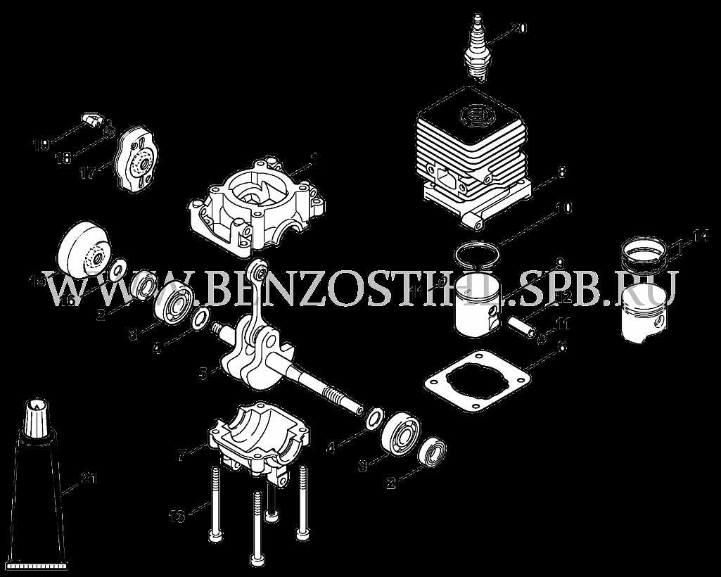
Each element in the representation is often accompanied by specific labels or numbers. These labels correspond to the component list, allowing you to match the visual with the actual part. Symbols and numbers are used to avoid confusion and ensure that each part can be easily identified and ordered when needed.
Understanding Component Placement
The layout typically shows how the parts interact with each other, outlining their position within the assembly. This can help you understand how the tool functions as a whole and make troubleshooting or repairs easier. Pay attention to the arrangement and connections between parts to see how everything fits together.