For anyone working with welding equipment, knowing the internal structure and understanding how each part functions is essential for optimal performance and longevity. Identifying and learning about the various elements of the system can significantly ease troubleshooting and repair tasks. With a clear grasp of these components, you can ensure smooth operation and prevent costly damage due to improper handling.
Proper maintenance and timely repairs are crucial to keep your equipment running efficiently. Whether you are replacing a broken element or simply performing routine checks, having access to a detailed visual reference can save time and reduce errors. In this guide, we will break down the important parts of your machine and explain how they work together to deliver the results you expect.
Understanding the layout of the internal components helps you identify any potential issues quickly. By becoming familiar with the structure, you’ll be able to manage your equipment more effectively, ensuring a longer service life and enhanced performance for all your welding projects.
Understanding the Welding Equipment

In any welding machine, the key to achieving precise and durable results lies in the coordination of various components. Each part, from the power supply to the nozzle, plays a distinct role in ensuring smooth operation and high-quality output. Understanding how these elements interact will not only improve your work but also help you maintain the equipment effectively.
How the Machine Operates
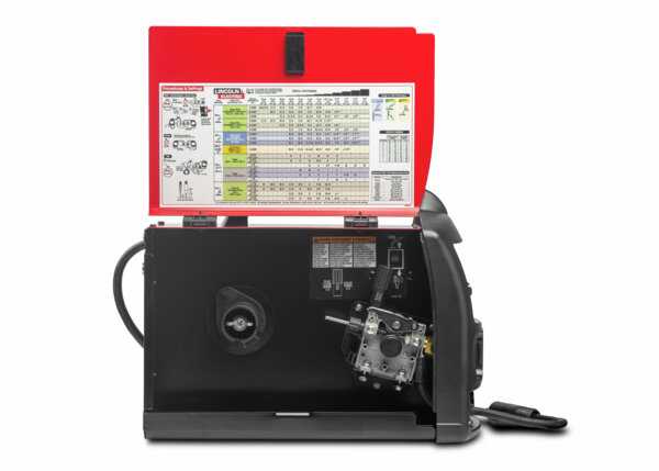
At the heart of the system, the power source provides the necessary current to facilitate the welding process. This is linked to the feed mechanism, which controls the delivery of welding material. Together, these two elements work in unison to create the heat and fusion needed for the welding process. By familiarizing yourself with their function, you can quickly identify any irregularities that might arise.
Common Features and Functionality
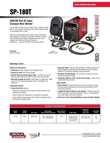
Welding machines come with a variety of features, including adjustable settings for voltage and wire speed, which give users control over the welding process. Understanding these features allows operators to fine-tune their equipment for different types of projects. Additionally, safety mechanisms such as circuit breakers and thermal protection are essential for preventing overheating or electrical faults, ensuring both user safety and the longevity of the machine.
Key Components in Welding Equipment

Every welding machine consists of a variety of essential elements, each with its unique function. Understanding these key components allows operators to troubleshoot issues, replace damaged parts, and perform routine maintenance with ease. By becoming familiar with the core structure of the device, users can enhance the machine’s efficiency and ensure optimal results during welding tasks.
Power Supply and Control System
The power supply serves as the heart of the system, providing the necessary energy to initiate and sustain the welding process. This component regulates the output current to maintain a consistent and stable arc. Alongside it, the control system allows users to adjust settings such as voltage and wire speed, offering flexibility for various types of welding applications.
Feeding Mechanism and Gun Assembly
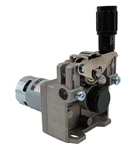
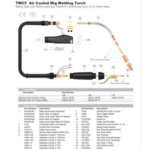
The feeding mechanism is responsible for continuously supplying welding wire to the arc. This element works closely with the gun assembly, which houses the nozzle, trigger, and wire feed components. These parts work together to deliver the material to the weld pool, ensuring the correct amount of filler material is applied for strong, reliable welds. Understanding the role of each element within this system is key to achieving precise and high-quality results.
How to Read the Equipment Layout
Understanding the layout of the internal components is crucial for efficient troubleshooting and maintenance. A well-structured visual reference provides a clear representation of how each element fits into the overall system. Learning to read and interpret these layouts can simplify repairs, allow for quicker part identification, and enhance your ability to perform routine checks effectively.
Identifying Components and Symbols
Most layout illustrations include a variety of symbols or labels that correspond to different parts within the system. These symbols are designed to help users easily locate specific elements like the power switch, feed mechanism, and cooling components. By becoming familiar with the commonly used symbols, operators can quickly navigate through the diagram and understand how each component functions within the larger assembly.
Understanding Component Connections

In addition to identifying individual parts, it is equally important to understand how these components are connected. Lines or arrows often indicate the relationships between different elements, showing how energy or materials flow through the system. Recognizing these connections can help users pinpoint issues, such as where a malfunction may be affecting the overall performance of the equipment.