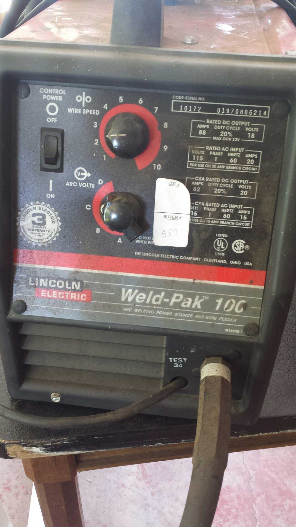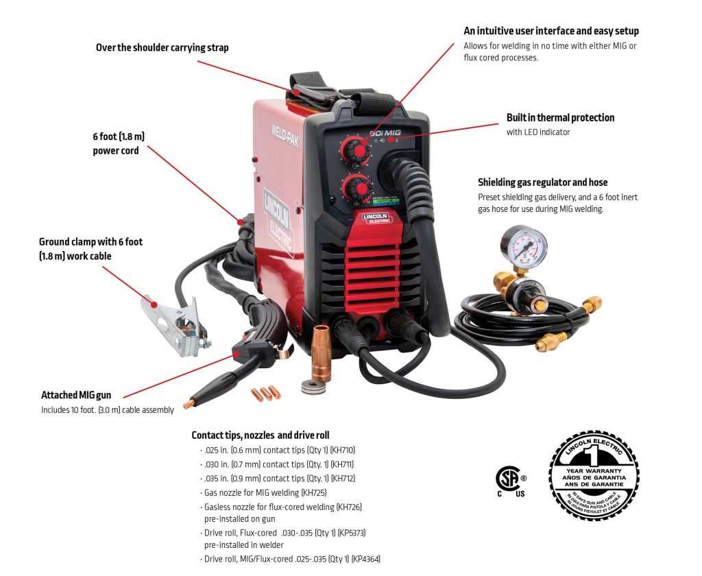
Every welder is made up of various essential elements that work together to provide reliable performance. Having a clear understanding of each component is key to maintaining and troubleshooting any machine effectively. Whether you’re a beginner or experienced user, knowing how these parts interact can save time and money in the long run.
In this guide, we will explore how to navigate the specific component layout of your welder. We’ll also provide insights into how each part contributes to the overall functionality. This knowledge is crucial for ensuring that your equipment continues to operate at its best, whether for routine use or during repair procedures.
By learning how to identify and replace key elements, you’ll be able to troubleshoot common issues and prevent more significant malfunctions. This understanding not only enhances your ability to repair the machine but also extends its lifespan, ensuring optimal performance for years to come.
Understanding Key Components of Your Welder
When working with any welding machine, it’s essential to have a solid understanding of the main components that make up the system. Each part plays a crucial role in ensuring that the machine functions effectively. Knowing how to identify and troubleshoot these elements can significantly impact your overall welding experience.
At the heart of the system are several core elements that work together to provide the power and stability needed for successful welding. By familiarizing yourself with these components, you can identify potential issues and keep your equipment running smoothly.
- Power Supply: The source that provides electrical energy to the entire system, enabling the welder to operate.
- Control Mechanism: This allows you to adjust settings such as power, wire speed, and voltage to achieve the desired results.
- Wire Feed System: Responsible for feeding the welding wire steadily to ensure consistent welds.
- Electrode Holder: The device that holds the electrode securely in place during operation.
- Cooling System: Ensures that the welder doesn’t overheat, maintaining safe and efficient performance over extended periods.
Understanding how each component interacts is vital for diagnosing issues and performing maintenance tasks. By knowing what to look for in these elements, you can take a more proactive approach in ensuring your equipment remains in top condition.
How to Read the Component Layout
Understanding how to interpret a component layout is a critical skill when working with any welding machine. The layout provides a visual representation of all the key elements, making it easier to identify each part and its function. By learning how to read this map, you can quickly pinpoint any issues and understand the relationship between different components.
Typically, the layout is organized with clear labels and connections, showing how each part fits into the overall structure. It may also highlight critical elements like electrical connections, cooling systems, or specific parts that require maintenance or replacement. Familiarizing yourself with these symbols and markings will allow you to navigate the layout effectively and make informed decisions when performing repairs or upgrades.
To get started, look for the following features in the layout:
- Labeling: Clear labels help you identify each part easily. Some layouts will use numbers or codes to reference each component.
- Color Coding: Different colors might indicate different types of components, such as electrical parts or mechanical systems.
- Connections: Lines or arrows typically show how parts are connected, helping you visualize the flow of power or materials within the machine.
- Exploded Views: Many layouts use exploded views, where parts are shown separated from the rest of the machine, to give you a better understanding of how everything fits together.
By carefully studying the layout, you’ll be able to identify each element’s role and gain valuable insights into how the system works as a whole. This understanding is essential for any troubleshooting or repair task, allowing you to work more efficiently and confidently.
Common Repairs Using the Component Layout

Repairing a welding machine often requires identifying which parts need attention. With a well-structured component layout, you can quickly locate the areas that need repair or replacement. Common issues such as electrical failures, feed system problems, or overheating can often be resolved by understanding how each part interacts and where potential faults might arise.
Using the component map, you can easily identify worn-out or malfunctioning parts. Here are some of the most common repairs that can be performed with the help of the layout:
- Wire Feed Issues: If the wire isn’t feeding properly, you can identify the feed motor, rollers, and related components in the layout to ensure everything is aligned and functioning smoothly.
- Power Supply Problems: Electrical issues such as insufficient power or inconsistent output are often traced back to the power supply components. The layout will show how these elements are wired together, allowing for quick diagnostics.
- Overheating: If your machine overheats, the cooling system is often the culprit. Use the layout to locate the cooling fan and heat sensors, ensuring they’re working properly and not clogged with debris.
- Broken Switches or Controls: Faulty switches or knobs can prevent proper operation. By referencing the component layout, you can identify the exact location of control components and replace or repair them as needed.
By utilizing the layout, you can streamline the repair process, saving time and reducing unnecessary disassembly. A good understanding of the machine’s internal components allows for faster troubleshooting and more effective repairs.