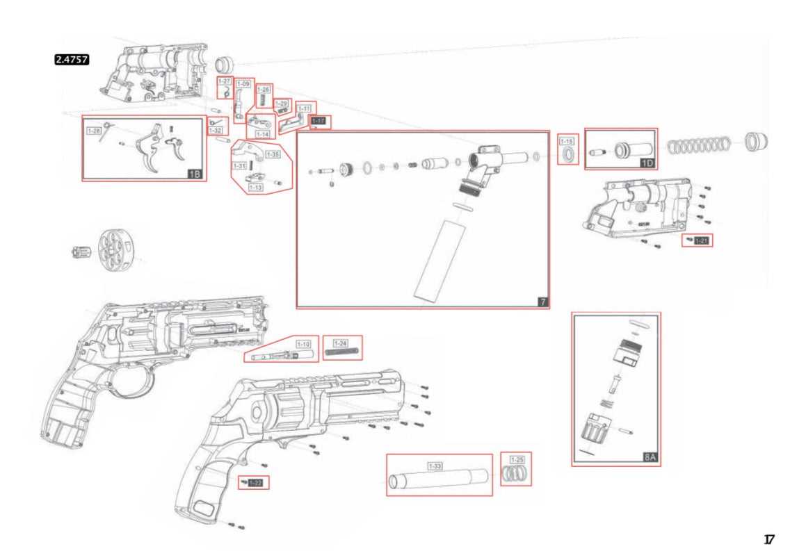
In the world of mechanical devices, having a clear understanding of how components fit together is essential for maintenance and repair. Visual guides that break down the assembly process offer valuable insights, helping both beginners and experienced technicians. These visual aids simplify complex structures and ensure that each part is correctly placed for optimal performance.
Whether you’re assembling, disassembling, or troubleshooting, referring to these illustrations can make the process more efficient. They provide a clear view of how individual elements interact, offering step-by-step instructions on reassembly. With proper understanding, any mechanical repair becomes more manageable, reducing the risk of errors and unnecessary complications.
Having access to such detailed illustrations empowers users to identify specific pieces and their roles. This not only aids in repairs but also helps in understanding the full functionality of a system, making future troubleshooting much easier. The ability to quickly pinpoint and address issues is invaluable in maintaining the longevity of any device.
Understanding Mechanical Assembly Guides
Having a clear and organized visual representation of a device’s construction is crucial for understanding its structure. These guides break down complex assemblies into simple, comprehensible steps, allowing users to visualize how each element fits together. This clarity makes it easier to follow through on repairs or upgrades without confusion.
The visual references provide a detailed view of how individual components interconnect. Each part is labeled, highlighting its position and relationship to other elements within the system. With this, it’s easier to identify worn-out pieces or areas that need attention during maintenance procedures.
For anyone attempting repairs or adjustments, such illustrations are essential tools. They remove much of the guesswork, offering clear instructions and insights into how to handle each component correctly. By understanding these visual aids, users can effectively address issues, ensuring the device operates smoothly and efficiently.
How to Interpret Assembly Schematics
Interpreting assembly schematics requires understanding how to read the visual representation of a mechanical system. These illustrations provide a detailed layout of the device, showing how each element connects and interacts with others. By studying the layout, you can identify the order of assembly and troubleshoot any issues that arise.
The key to interpreting these guides lies in recognizing the symbols and markings used to represent each component. Different lines, shapes, and numbers are employed to indicate the specific function or position of parts. Understanding these symbols will allow you to trace connections and ensure that everything fits correctly in the system.
Once familiar with the schematic layout, it becomes easier to spot any potential problems. Whether you’re replacing a broken piece or assembling a device from scratch, these guides act as a valuable reference. They help to prevent mistakes by clearly showing how each part should be positioned in relation to the others.
Common Components in Mechanical Models
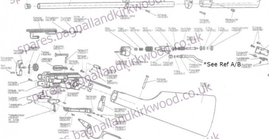
When working with mechanical systems, it’s important to recognize the key elements that make up the structure. These components work together to ensure the device functions smoothly. Each piece has a specific role, whether it’s providing support, enabling movement, or facilitating other essential functions. Understanding these elements helps users maintain and troubleshoot the system effectively.
Core Functional Components
At the heart of many devices are core functional elements such as springs, seals, and levers. These components are often subject to wear and tear, so understanding their role and recognizing when they need replacing is crucial for the longevity of the system. Springs help with tension and movement, while seals maintain pressure and prevent leakage, ensuring the device operates efficiently.
Supporting Elements
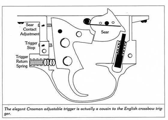
Supporting components, like screws, washers, and brackets, are often overlooked, yet they play a critical role in keeping everything in place. These elements provide stability, securing other pieces together and ensuring that no part is out of alignment. Proper maintenance of these supporting parts is just as essential as maintaining the core functional components to ensure optimal performance.
Key Parts and Their Functions
Understanding the core elements of any mechanical system is essential for efficient operation and maintenance. Each component plays a specific role that contributes to the overall functionality of the device. Recognizing these key pieces and their functions allows users to troubleshoot issues, perform repairs, and ensure the device performs at its best.
Moving and Operating Elements
Moving components, such as gears, pistons, and triggers, are responsible for enabling the main actions of the device. Gears transfer motion and force, pistons facilitate power generation or movement, and triggers activate mechanisms. These elements are crucial in making sure that the device performs its intended function accurately and consistently.
Support and Stabilizing Components
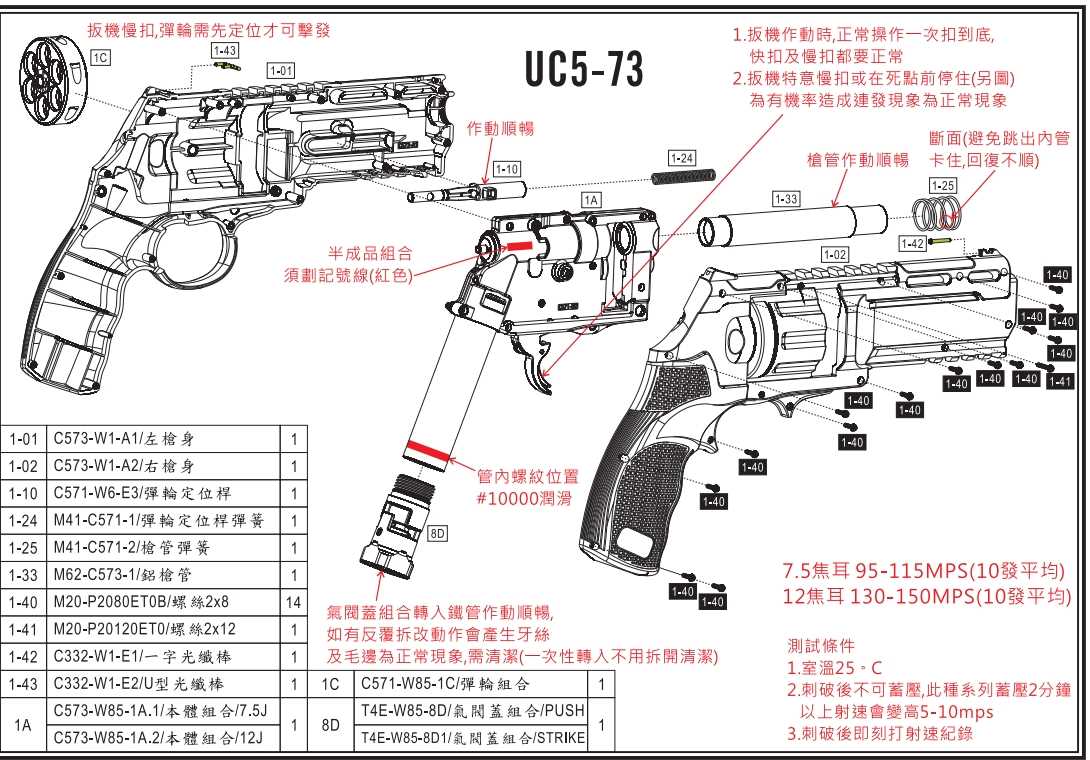
Support elements, including frames, brackets, and fasteners, help to keep everything securely in place. These parts ensure that moving components stay aligned, preventing misfires or malfunction. By providing structural integrity, support components are essential for maintaining the stability and durability of the system throughout its use.
Step-by-Step Guide to Repairs
Repairing a mechanical device requires careful attention to detail and a clear understanding of the assembly. By following a structured process, users can efficiently identify issues, replace faulty components, and restore the system to its optimal state. A well-organized approach ensures that repairs are done properly and with minimal risk of causing further damage.
Preparing for the Repair
Before starting any repair, it’s essential to gather the necessary tools and identify the faulty components. A thorough assessment will guide you in determining which elements need attention. Here’s a quick checklist to ensure you’re ready for the task:
- Ensure the device is powered off and safely disassembled.
- Have the appropriate tools on hand, including screwdrivers, wrenches, and any specialized equipment.
- Inspect the device to identify damaged or worn components.
- Keep replacement parts available for quick access during the process.
Performing the Repair
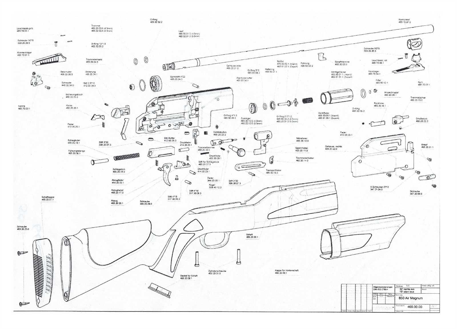
Once you’re prepared, follow these steps to replace the faulty components and restore the system:
- Begin by removing the damaged part carefully, following the guidance from assembly illustrations.
- Clean the area around the removed component to ensure no debris interferes with the new piece.
- Install the replacement component, making sure it’s properly aligned and secured.
- Test the device after reassembly to confirm the repair was successful.
By following these steps methodically, you can effectively complete the repair and ensure that the device functions properly once again.