When it comes to vehicle performance, the intricate network of components responsible for smooth shifting is critical. The structure that governs these movements consists of numerous interdependent elements, each contributing to the overall functionality. Gaining an understanding of how these pieces fit together can significantly enhance both the repair process and the efficiency of the machine.
Identifying each element and understanding its role allows technicians and enthusiasts alike to better diagnose issues, optimize performance, and ensure longevity. This knowledge is vital for anyone working on mechanical systems or simply looking to deepen their understanding of automotive technology.
Whether you’re trying to troubleshoot a malfunction or learn more about the design, knowing how to interpret the layout of these interconnected components can make all the difference. A closer look reveals the complexity behind every shift and how these elements interact to create a seamless experience.
Understanding the 4L60E Transmission System

Modern automotive systems rely on a carefully engineered set of mechanisms to control gear shifting. These systems ensure that the vehicle operates efficiently across a variety of conditions, from smooth cruising to rapid acceleration. The structure behind this functionality is complex, with each component playing a vital role in maintaining the balance and performance of the overall system.
How the Gear Mechanism Works

The gear mechanism within this system is designed to facilitate smooth changes between different speeds, allowing for optimal engine performance. It operates through a series of interlinked components that engage and disengage as needed, based on factors such as vehicle speed and load. Understanding how these elements function together is key to grasping the overall system design and the necessary adjustments for proper operation.
Role of Hydraulic and Electrical Systems

In addition to the mechanical components, the system incorporates hydraulic and electrical systems that further enhance control and precision. Hydraulic fluid is used to activate specific elements at the right time, ensuring seamless transitions between gears. Electrical systems manage signals and feedback to control the hydraulic flow, making the entire operation more responsive and adaptable to driving conditions.
Key Components in the 4L60E Assembly

The efficiency and reliability of a vehicle’s shifting system depend heavily on the interaction between various key components. Each element works in unison to ensure smooth operation, with specific roles designed to manage and control speed transitions. Understanding these critical elements helps in diagnosing issues and performing effective repairs or upgrades.
The Hydraulic System
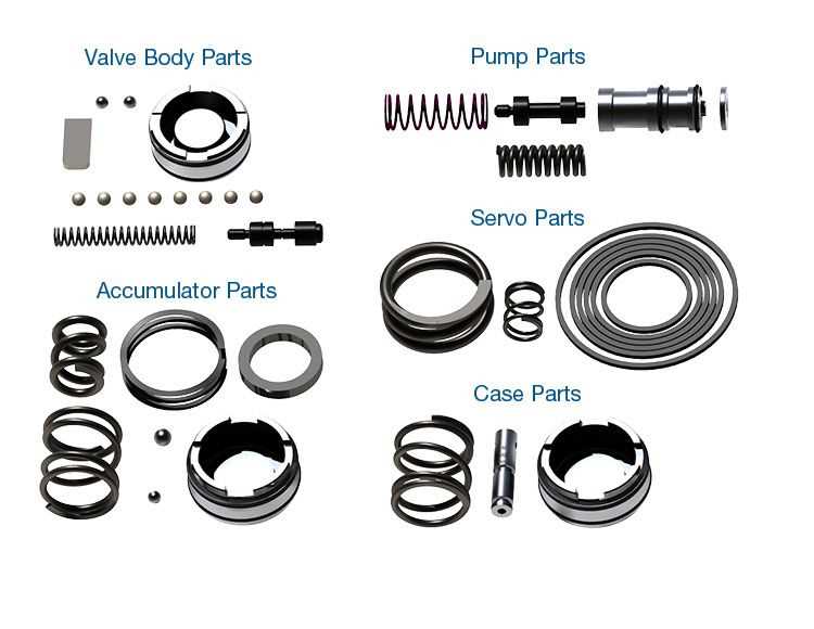
One of the most crucial systems involved is the hydraulic mechanism. It uses fluid to control the movement of internal components, such as the clutch packs and valves. This system operates under high pressure, delivering the necessary force to engage and disengage different gears. Hydraulic fluid flow is tightly regulated to ensure that shifts are executed at the right time, contributing to the overall smoothness of the driving experience.
Clutch Packs and Bands
Clutch packs and bands are vital for the proper engagement of gears. These components act as friction elements, holding certain gears in place or allowing them to shift smoothly. The clutch packs consist of multiple friction plates that work together to connect or disconnect shafts, while the bands help control the timing and pressure of these shifts. Together, they ensure that gear transitions occur seamlessly, with minimal power loss and wear.
How to Interpret the Transmission Parts Diagram
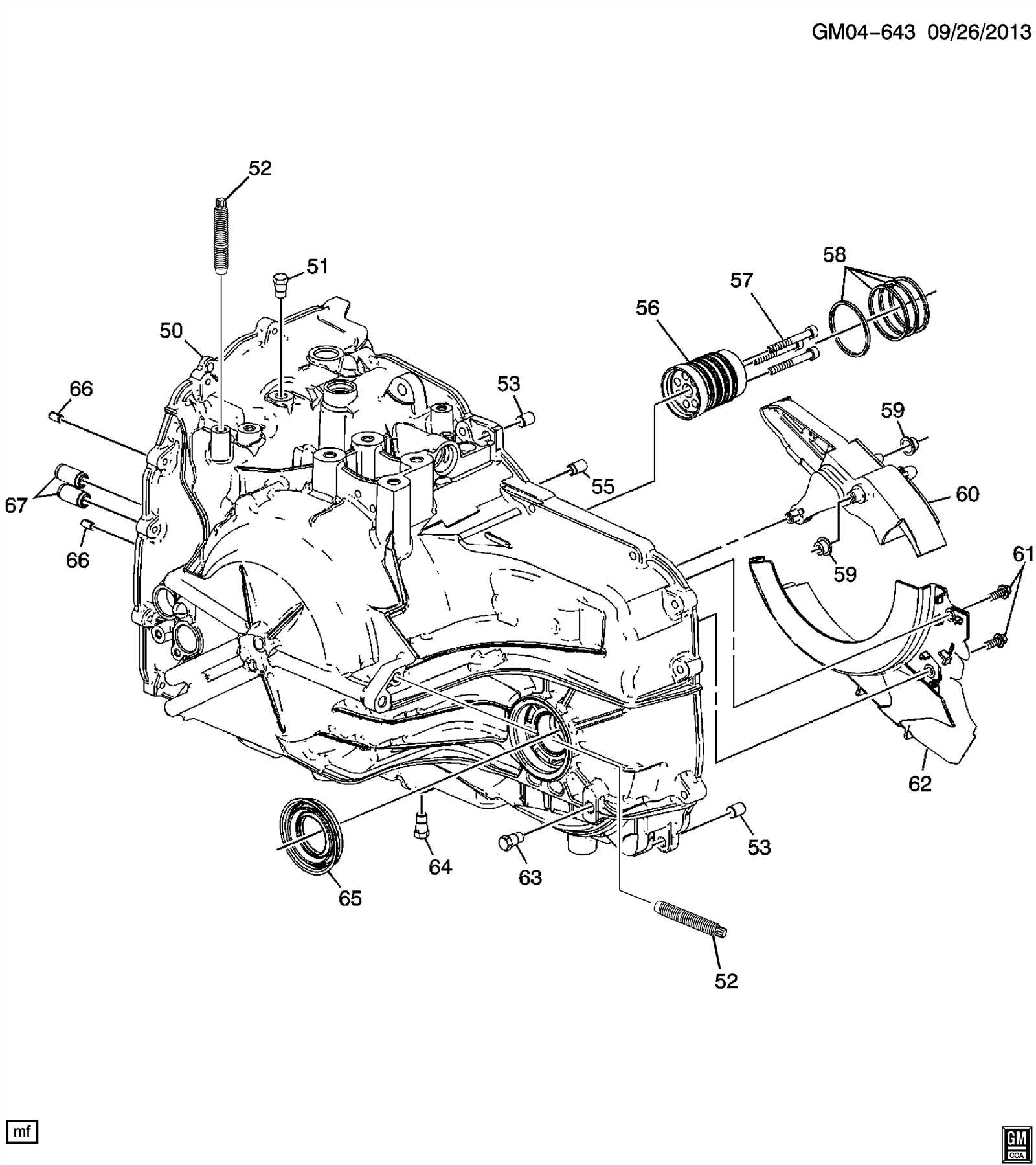
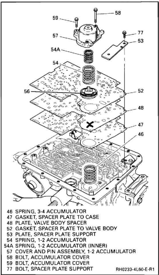
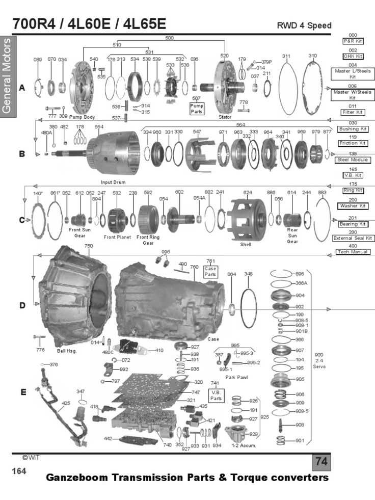
Understanding the layout of a vehicle’s gear system is essential for diagnosing issues and performing maintenance. A detailed illustration of the internal components provides valuable insights into how each element fits together and interacts with others. By interpreting these illustrations correctly, you can gain a clearer understanding of the function and location of every key component, which aids in both repairs and upgrades.
The diagram typically includes various symbols and labels that represent different mechanical elements, such as gears, valves, and hydraulic components. Each symbol corresponds to a specific function or part of the system, and understanding these notations is crucial. Pay close attention to the connections between elements, as they illustrate the flow of power and fluid through the system, guiding how each component contributes to the overall operation.
When analyzing the diagram, take note of the flow paths and the sequence in which elements engage. Understanding how power is distributed and controlled throughout the system will help you identify potential weak points or areas of concern. Additionally, some diagrams may highlight critical maintenance points, such as where fluid should be checked or specific parts that require regular service.