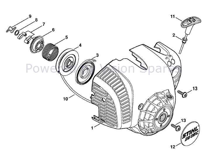
When it comes to maintaining outdoor power tools, having a clear understanding of their individual elements is essential for proper upkeep and repairs. A well-organized schematic can make all the difference, ensuring users can identify each part easily and avoid costly mistakes during maintenance. In this guide, we’ll walk you through the key aspects of your blower’s internal structure, helping you gain a deeper understanding of its functioning.
Whether you are a seasoned technician or a beginner, knowing how to interpret technical drawings of your equipment can save time and effort. These visual references provide clarity, enabling you to identify parts that may need replacing or servicing. By following this guide, you’ll be equipped to troubleshoot and perform maintenance tasks with confidence, keeping your tool in top working condition for years to come.
Understanding Equipment Component Layout
When handling outdoor power tools, a visual representation of their internal structure can greatly simplify maintenance and repair processes. These layouts offer a clear depiction of each individual element, allowing users to pinpoint exactly what they need to address. Understanding this layout is crucial for both novice and experienced users to carry out repairs with precision and efficiency.
Each component in a tool’s schematic is typically numbered or labeled, guiding users through the various sections of the equipment. The layout helps in understanding how different pieces interact, which can be particularly useful when troubleshooting issues or replacing worn-out parts. The following points highlight key elements to pay attention to when reviewing such visual guides:
- Component Identification: Each element is clearly marked, allowing for quick identification of specific parts that may need attention.
- Functional Relationships: Understanding how the different sections work together helps in diagnosing potential issues.
- Assembly Order: The layout often includes a recommended sequence for reassembling components after maintenance or repairs.
- Common Problem Areas: Some sections of the schematic may highlight components that are most prone to wear and tear, giving users an idea of what to check regularly.
By becoming familiar with these visual representations, users can approach maintenance tasks with greater confidence, ensuring their equipment remains functional and reliable for extended periods.
Identifying Key Components of BG86C Blower
Properly identifying the essential elements within your blower is fundamental for efficient maintenance and repair. Each component plays a specific role in the overall function, and recognizing these parts can save time when diagnosing issues or performing repairs. In this section, we’ll focus on the primary components that should be regularly inspected and understood for optimal tool performance.
Critical Internal Mechanisms
The heart of the blower consists of several internal mechanisms that work together to create powerful airflow. These components include the engine, fan, and air intake system. Understanding how each part contributes to the blower’s function helps in recognizing potential malfunctions or areas in need of replacement.
- Engine: Powers the blower and drives all internal systems.
- Fan: Responsible for generating the strong airflow needed to clear debris.
- Air Intake: Ensures the engine receives the proper amount of air for combustion.
External and Supporting Parts
In addition to the internal components, there are several external and supporting parts that help maintain the functionality of the blower. These include the trigger mechanism, nozzle, and the housing. Each of these elements can wear down over time and may require regular inspection to ensure the blower operates effectively.
- Trigger: Controls the speed and intensity of airflow.
- Nozzle: Directs the airflow to specific areas for precise cleaning or clearing.
- Housing: Protects internal components and ensures safety during operation.
By understanding these key components, users can effectively maintain their equipment and address any issues before they impact performance.
How to Use the Parts Diagram for Repairs
Having a clear, detailed schematic of your tool can make repairs much more manageable. These visual guides help users identify damaged or worn components, determine their correct placement, and ensure the right steps are taken during the repair process. Knowing how to navigate such a diagram is essential for performing repairs accurately and efficiently.
Step-by-Step Identification
When using a visual guide for repairs, the first step is to locate the part you are working on. The diagram typically includes labeled sections that correspond to each part of the equipment, making it easy to find what needs attention. Once you’ve located the necessary component, it’s important to check the associated details, such as part numbers or specifications, to ensure the correct replacement item is used.
- Locate the section: Find the part you need by referencing the diagram’s labeled sections.
- Verify specifications: Cross-check part numbers and details to ensure compatibility with replacement parts.
- Examine relationships: Understand how the component fits into the larger system for proper installation.
Disassembly and Reassembly
Once you’ve identified the faulty or worn-out part, the schematic can guide you through the disassembly and reassembly process. These guides often include arrows and instructions on how to remove and install components in the correct order, ensuring that no part is missed or incorrectly positioned. Following the diagram closely will minimize errors and improve repair efficiency.
- Disassemble carefully: Follow the guide to remove each part in the correct sequence.
- Reassemble methodically: Use the diagram to ensure all parts are correctly placed back in position.
By utilizing the visual layout for both disassembly and reassembly, users can effectively perform repairs with confidence, restoring the tool to peak performance.