When maintaining or repairing tools, it is essential to understand the layout of their individual components. Knowing how each part fits together helps identify issues, order replacements, and ensure proper reassembly. This guide focuses on the inner workings of such devices, providing clarity on their structure and functionality.
Each machine consists of various elements that work in harmony to achieve its purpose. Familiarity with these elements, their locations, and how they interact can simplify the process of diagnosis and repair. Whether you are troubleshooting or replacing worn-out pieces, a clear visual representation of the components can be invaluable.
In this article, we will explore the key components of the tool, offering insight into how to approach maintenance tasks efficiently. Understanding these details will empower you to make informed decisions when dealing with mechanical failures or upgrades.
Understanding Tool Components
Every tool is designed with a series of interconnected elements, each playing a specific role in its overall functionality. Gaining a deeper understanding of these components is crucial for anyone looking to perform maintenance, troubleshooting, or replacement tasks. Recognizing how each piece contributes to the tool’s performance can significantly improve your ability to fix or enhance its operation.
Main Structural Elements

The core structure of the device includes its housing, motor, and other major assemblies. These elements provide the framework and power needed for the tool to function. The motor, for instance, is responsible for driving movement, while the housing protects internal mechanisms from damage and exposure. Knowing how these parts interact ensures that any issues affecting the tool’s basic operation can be diagnosed and addressed effectively.
Functional and Supporting Components
Along with the primary elements, supporting components like switches, belts, and connectors play an essential role in the tool’s overall operation. These smaller yet crucial parts ensure smooth transitions between functions and allow the tool to adapt to different tasks. By understanding the purpose and location of these supporting elements, you can quickly identify wear and tear or other problems that may arise over time.
How to Read the Assembly Layout

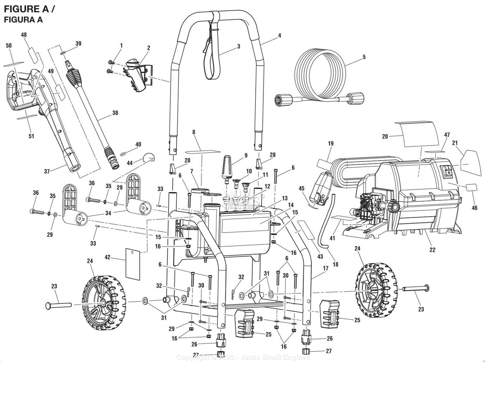
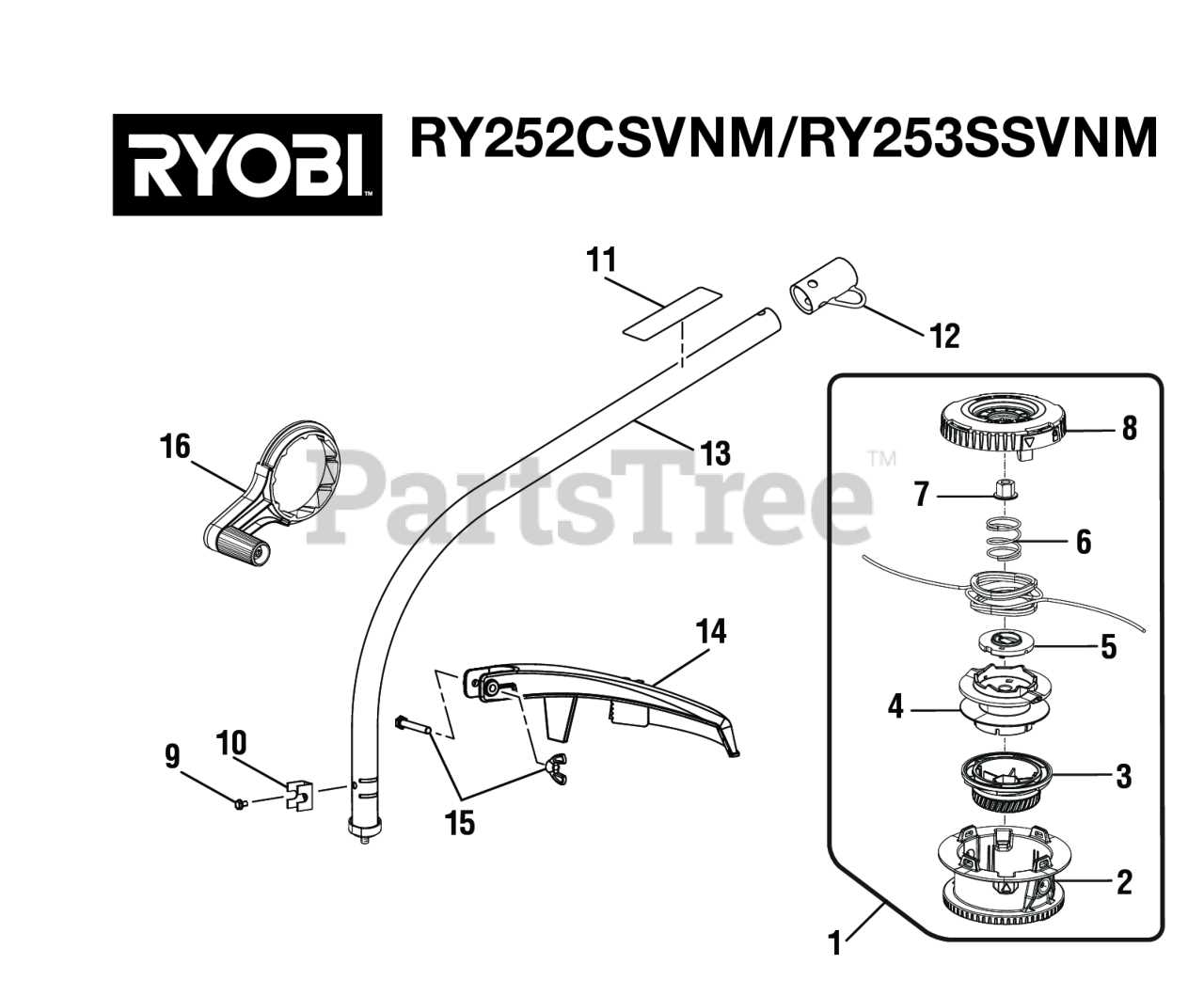
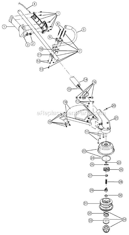
Interpreting a detailed layout of a tool’s components is essential for effective maintenance and repair. These illustrations provide a visual representation of the tool’s internal and external elements, making it easier to identify individual pieces and understand their relationships. Learning how to read these layouts ensures you can locate the right parts quickly when performing repairs or replacements.
Key Features to Identify
When viewing an assembly layout, there are several features to pay attention to:
- Part Labels: Each component is usually assigned a unique identifier, such as a number or letter, which corresponds to the list of components.
- Groupings: Elements are often grouped together based on function, making it easier to identify areas that may require attention.
- Connections: Pay close attention to lines or arrows that indicate how parts connect or interact with each other.
Steps for Effective Use
To make the most of the assembly layout, follow these steps:
- Locate the part number or label in the diagram and match it with the corresponding entry in the parts list.
- Identify the surrounding components that might affect or be affected by the piece you are replacing.
- Check for any special instructions regarding assembly or disassembly, which are often provided in the diagram for easier handling.
Common Issues and Parts Replacement

Like any tool, regular use can lead to wear and tear, causing various malfunctions. Recognizing the most common issues early on and understanding which components need replacement is key to keeping the tool in optimal working condition. Identifying problems and addressing them promptly can help prevent more serious damage and extend the life of the tool.
One of the most common issues involves the failure of internal components such as the motor, which may stop functioning due to overheating or wear. Another frequent problem is with the switches or connectors, which can become damaged over time, affecting the tool’s performance. Additionally, external elements like the housing or handles may crack or become loose, compromising both safety and functionality.
When replacing worn or damaged components, it’s important to follow the manufacturer’s specifications to ensure compatibility and avoid further issues. Referencing the tool’s assembly layout helps pinpoint the exact piece that needs to be replaced and guides you through the proper installation process. By staying proactive with replacements, you can maintain peak performance and prevent unnecessary downtime.