Proper maintenance and repair of mechanical devices require a clear understanding of their individual components and how they work together. Knowing the layout and functions of each part allows users to effectively troubleshoot and replace faulty elements, ensuring longevity and peak performance.
In this section, we will explore a detailed guide to the essential elements of a specific equipment model. You will learn how to interpret the layout, identify key components, and follow a systematic approach to resolving common issues that may arise during use. This approach ensures that repairs and adjustments are made with precision and care.
By familiarizing yourself with the essential parts and their connections, you gain valuable insight into the inner workings of the device. Whether you’re performing routine maintenance or tackling more significant issues, understanding the design will make your tasks more manageable and efficient.
Overview of Equipment Components

Every mechanical system is made up of numerous interdependent elements that work in unison to ensure proper functionality. Understanding the different components involved is crucial for effective maintenance and repair. In this section, we will look at the key elements that make up the equipment, their roles, and how they interact to deliver optimal performance.
Major Components and Their Functions
The equipment consists of several important units, each serving a unique function. Below is a list of the most critical elements and their roles in the system:
- Motor: Powers the system and drives the motion required for operation.
- Control Unit: Regulates the performance and settings of the device, ensuring correct operations.
- Structural Frame: Provides the necessary support for all components and absorbs external forces during use.
- Transmission Mechanism: Transfers energy from the motor to other moving parts, enabling the desired function.
- Power Supply: Delivers the required energy to various components, ensuring consistent performance.
Understanding the Layout of Components
The layout of the components plays a significant role in their operation. The design ensures that all elements are strategically placed for maximum efficiency and ease of maintenance. Understanding the system’s layout helps users identify issues and perform necessary repairs without causing further damage.
- The motor is typically located at the core of the system for easy energy transfer.
- The control unit is often placed near the interface for quick access to settings.
- The transmission mechanism is positioned to efficiently transfer energy to moving parts.
Understanding Key Parts in the Diagram
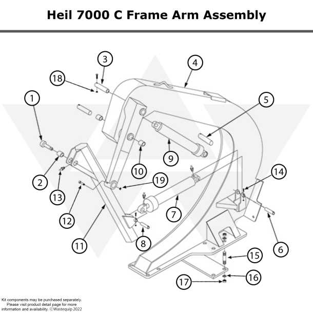
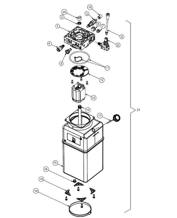
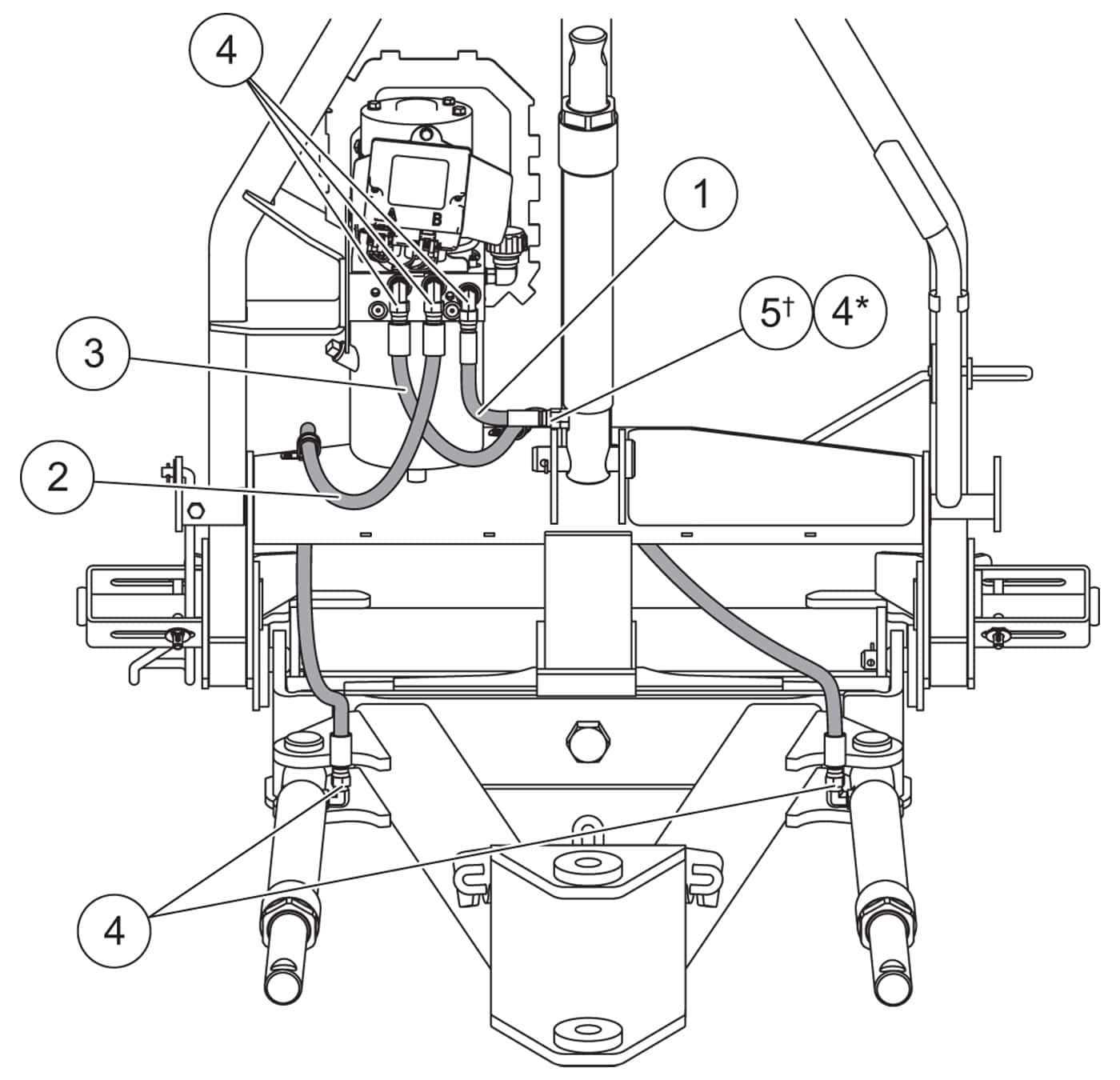
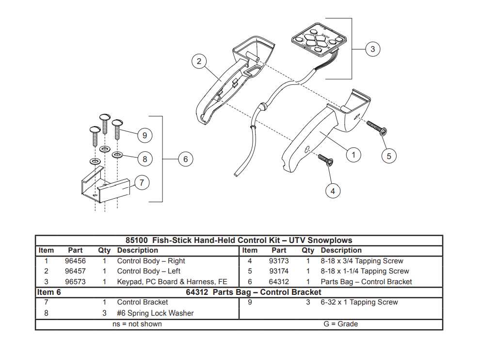
Analyzing the structure of any complex system requires a clear understanding of its essential components and their respective roles. This section focuses on the most significant elements of the equipment, helping users to identify and comprehend how each part contributes to the overall functionality. By recognizing these key elements, you can perform maintenance or repairs more effectively.
Each part serves a specific function and is positioned in a way that allows for optimal interaction with other elements. Understanding these connections is vital for troubleshooting and making precise adjustments to the system. Whether it’s a power source, a transmission component, or a control unit, each element has a unique role that supports the performance of the entire device.
To make the most of this information, it’s important to familiarize yourself with the layout of the components and how they are represented. This knowledge helps you to identify any potential issues and know where to focus your efforts during repair or maintenance tasks.
How to Read the Equipment Layout
Understanding how to interpret a system’s layout is essential for anyone looking to perform maintenance or repairs. The visual representation of the system offers valuable insight into how the components are arranged and interact with each other. In this section, we will discuss how to effectively read and use the layout to identify key elements and diagnose potential issues.
Begin by familiarizing yourself with the symbols and labels used in the diagram. Each component is usually marked with a clear identifier, often accompanied by a brief description of its function. The connections between these elements are also important to note, as they indicate how energy, signals, or materials flow through the system.
By carefully studying the layout, you can gain a deeper understanding of the entire structure and identify where problems may arise. Whether you’re troubleshooting, replacing parts, or upgrading the system, being able to read the layout accurately will save time and improve your overall efficiency.
Step-by-Step Guide for Assembly
Assembling mechanical equipment can seem like a daunting task, but breaking it down into manageable steps makes the process easier and more efficient. This section provides a detailed guide to help you put together the system by following a structured approach. With clear instructions and attention to each phase of the process, you can ensure that everything is assembled correctly and securely.
Preparation and Initial Steps
Before beginning the assembly, ensure you have all the necessary components and tools on hand. It is important to follow the correct sequence to prevent errors and avoid damage to parts. The first few steps typically involve setting up the base structure and securing the major units that support the system’s operation.
Assembly Process Breakdown

Follow these key steps to assemble the system effectively:
| Step | Action | Details |
|---|---|---|
| 1 | Base Frame Setup | Begin by securing the main structural elements to form the foundation of the system. |
| 2 | Install Power Source | Connect the power supply components, ensuring proper placement and alignment. |
| 3 | Connect the Control Unit | Position and attach the control panel, making sure all wiring is correctly installed. |
| 4 | Attach Moving Parts | Carefully connect all moving components, such as the transmission and mechanisms that will facilitate motion. |
| 5 | Final Checks | Inspect all connections, tighten fasteners, and ensure everything is properly aligned before operation. |
By following these steps and taking your time, you will achieve a successful and efficient assembly, ready for use or testing. Always refer to the specific guidelines provided to avoid mistakes and ensure optimal performance once the setup is complete.
Common Issues and Part Replacements

Like any mechanical system, equipment can experience various issues over time due to wear, improper use, or environmental factors. Understanding the most common problems that can occur and knowing how to replace the affected components is essential for maintaining optimal performance. This section covers frequent issues and the corresponding steps for replacing the malfunctioning elements.
One of the most common problems is malfunctioning components that prevent the system from operating efficiently. These issues can often be traced to wear and tear on critical elements like motors, connectors, or seals. Recognizing these symptoms early can save time and effort by allowing you to replace the faulty part before it causes more damage to the entire system.
For effective repairs, it’s important to know which components need replacing and how to do so properly. Following the manufacturer’s guidelines for part compatibility and installation ensures that the new elements work seamlessly with the rest of the system. Regular checks and timely part replacements can extend the lifespan of your equipment and prevent unexpected failures.