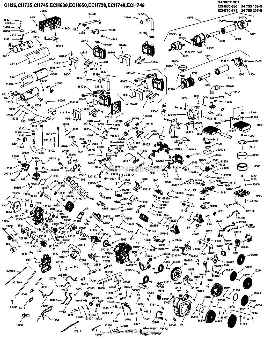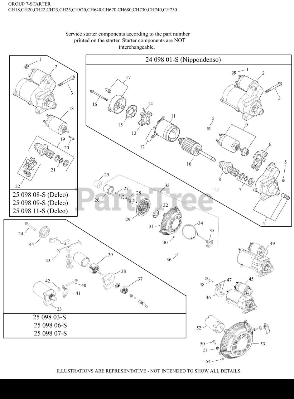
When it comes to maintaining and repairing a high-performance power unit, having a clear visual reference is crucial. Knowing the exact configuration of each individual element helps ensure smooth operation and reduces the likelihood of errors during maintenance. With a structured overview, you can identify and address issues promptly, saving time and effort in the long run.
Understanding the internal structure of the power system involves recognizing how different components interact. A detailed map of the various sections gives you insight into how the entire assembly works together. From the combustion chamber to the smaller mechanical features, this layout serves as a roadmap to effective servicing.
Whether you are troubleshooting a malfunction or conducting routine maintenance, having an organized guide will streamline your approach. This allows you to efficiently locate problem areas and ensure that all parts are functioning as intended. By following a structured visual guide, you can enhance the longevity and performance of your system.
Understanding the 27 HP Power Unit
The 27 HP power unit is a robust and reliable system designed for various heavy-duty applications. It combines efficiency with durability, making it ideal for tasks requiring consistent performance over long periods. The system’s design focuses on maximizing output while minimizing fuel consumption, ensuring it meets the demands of both small and large-scale operations.
At its core, this setup relies on precise coordination between several key elements, each contributing to the overall functionality. The combination of mechanical parts, fuel management, and electrical systems work together seamlessly to provide the necessary force for a wide range of machinery. Understanding the layout of these components is crucial for proper handling and maintenance.
By familiarizing yourself with the design and configuration of the unit, you can troubleshoot common issues more effectively and ensure that each part performs optimally. Regular inspection and upkeep are essential to maintaining the system’s efficiency and extending its service life.
Key Components of the Power System
Understanding the critical components of a power unit is essential for effective operation and maintenance. Each individual part plays a specific role in ensuring smooth performance, from generating energy to distributing it to other systems. These key elements are intricately designed to work together, making the overall system efficient and reliable for various applications.
Among the most crucial components are the ignition system, fuel delivery mechanism, and the air intake. The ignition system sparks the combustion process, while the fuel delivery system ensures the correct mixture of air and fuel reaches the combustion chamber. The air intake filters and channels air to maintain optimal combustion conditions. Additionally, components like the cooling system and exhaust system help regulate temperature and emissions, ensuring the unit operates without overheating or excessive pollution.
Each of these parts needs to be regularly inspected to maintain optimal performance. Understanding their layout and function will assist in identifying potential issues early, allowing for prompt repair and minimizing downtime.
How to Use the Parts Layout
A clear and organized visual guide is essential for understanding the structure of a power unit. It allows users to easily identify components, their connections, and placement within the assembly. Knowing how to read and interpret this guide is key to efficient troubleshooting and maintenance.
To get the most out of the layout, follow these steps:
- Familiarize Yourself with the Overview – Begin by studying the full view of the unit, paying attention to the arrangement of major components.
- Locate the Sections – Break down the system into smaller sections to focus on specific areas like the ignition or fuel system.
- Identify Key Parts – Use the visual representation to identify individual parts within each section, noting their functions.
- Understand the Relationships – Look for connections between different parts and how they work together to achieve overall performance.
By following these steps, you can effectively use the layout to assist in repairs or routine inspections. It helps ensure all components are properly maintained and in good working order, preventing unnecessary downtime.
Step-by-Step Guide for Repairs
Repairing a power unit requires a clear approach and a well-structured plan. With the right knowledge and a methodical process, you can address any issues and restore the system to its optimal working condition. A detailed guide ensures that you don’t miss any critical steps and that all components are thoroughly checked during the repair process.
Preparation and Initial Inspection
Before starting the repair, ensure that you have all necessary tools and replacement parts. Begin by carefully inspecting the unit, checking for visible damage or signs of wear. Look for issues such as leaks, cracks, or loose connections that may be affecting the performance. Pay attention to any abnormal noises or malfunctions, as these can indicate specific problems within the system.
Executing the Repair
Once you’ve identified the problem areas, follow a step-by-step approach to address each issue. This could involve disassembling certain sections, replacing worn-out components, or cleaning parts that are clogged or dirty. Always follow the manufacturer’s recommendations for proper handling and installation of new parts. After the repair is completed, thoroughly test the system to ensure everything is functioning as expected.
Common Issues with Power Units

Even the most reliable systems can encounter problems over time, especially with frequent use. Recognizing common issues early can help prevent more serious damage and keep the unit running smoothly. By understanding the typical challenges faced by these power systems, you can address them promptly and minimize downtime.
Below is a table outlining some of the most frequent issues, their potential causes, and recommended solutions:
| Issue | Potential Cause | Recommended Solution |
|---|---|---|
| Overheating | Blocked cooling system, low coolant levels | Clean air vents, check and top up coolant |
| Starting Failure | Faulty ignition system, weak battery | Replace spark plugs, check battery voltage |
| Loss of Power | Clogged fuel filter, damaged air intake | Replace fuel filter, clean or replace air filter |
| Unusual Noises | Loose parts, damaged bearings | Tighten loose components, replace worn bearings |
By addressing these common issues early and performing regular maintenance, you can ensure the longevity and efficiency of your power unit. Always refer to the system’s manual for specific troubleshooting advice tailored to your model.