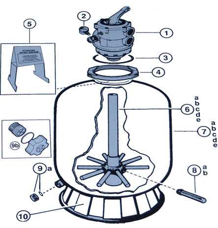
When working with complex mechanical systems, having a clear overview of each component and its relation to others is crucial for efficient repair and maintenance. A detailed visual reference can make it much easier to identify specific parts and understand their functions within the whole structure.
Knowing the layout and interconnections between different elements helps to pinpoint issues faster, reducing downtime and preventing costly mistakes. A well-organized schematic serves as a roadmap, guiding you through the intricate details of a machine’s construction.
In this guide, we will explore the key features of such visual tools, focusing on how they can enhance your understanding and improve maintenance tasks. Whether you’re a professional technician or a DIY enthusiast, mastering these resources will significantly streamline your work process.
Understanding the Sp0714t Parts Diagram
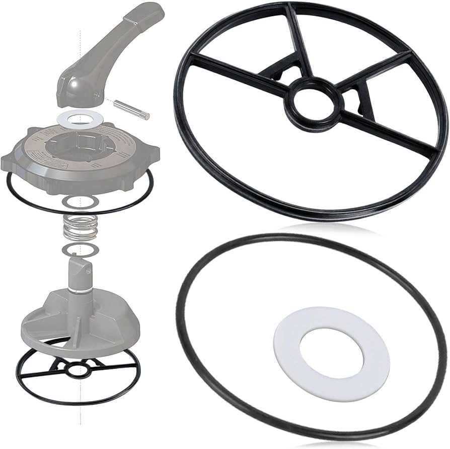
Having a clear visual representation of a machine’s structure is essential for proper troubleshooting and assembly. These detailed illustrations allow users to easily identify the different components and their positions within the system, providing valuable insights into how everything works together.
Breaking down the components on a schematic enables users to understand the flow of operations and pinpoint issues quickly. By studying each part’s function and relationship with other elements, one can grasp how a malfunction in one area might affect the overall system.
Furthermore, these guides are particularly useful for maintenance and repair tasks, as they provide accurate references that make disassembly and reassembly more efficient. With clear labels and well-organized sections, such visual tools ensure minimal errors and reduce the time spent searching for specific components.
How to Identify Sp0714t Components
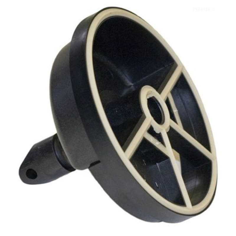
Identifying individual elements within a mechanical system can be a challenging task, especially when dealing with complex designs. A well-structured guide can significantly simplify the process by offering clear visual cues and labels, allowing users to quickly locate and understand the function of each component.
Study the Visual Representation
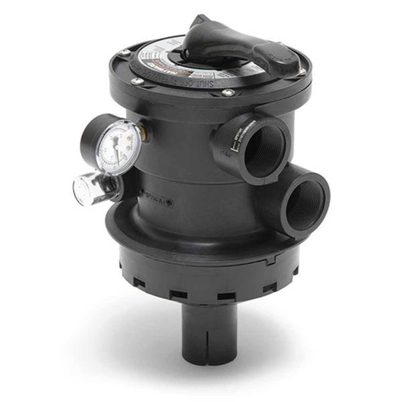
First, examine the provided visual representation carefully. Each part is typically marked with labels or numbers that correspond to a key, which can give you the specific details about the component’s name and its function within the larger structure.
Understand the Relationships Between Parts
It’s important to understand how different components interact with each other. By recognizing the connections between parts, you can better diagnose issues and grasp the flow of operations. Pay attention to how elements are positioned relative to each other, as this will give you insight into their purpose and the overall functioning of the system.
Benefits of Using the Sp0714t Diagram
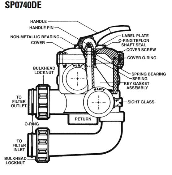
Utilizing a detailed visual guide for a complex system offers numerous advantages, particularly when it comes to simplifying maintenance and repair processes. These illustrations provide clarity and precision, ensuring that users can identify the correct components and understand their relationships within the machinery.
One of the key benefits is the reduction of errors during assembly or troubleshooting. With a clear reference, users can follow a step-by-step approach, minimizing the chances of overlooking or misplacing parts. Additionally, this type of resource speeds up the repair process by providing direct access to necessary information without requiring extensive prior knowledge of the system.
Furthermore, such guides improve efficiency by offering an organized structure that saves time when locating specific elements. For both beginners and experienced technicians, these references serve as a valuable tool for ensuring accuracy and effectiveness in each task.