In any vehicle, the control system responsible for maneuvering plays a crucial role in ensuring smooth and precise driving. This system consists of various elements that work in unison to offer stability and ease while navigating different road conditions. Familiarity with these components is essential for any owner or mechanic who needs to troubleshoot or maintain the system effectively.
Accurate comprehension of each individual element within this assembly can simplify the process of diagnosing issues and performing repairs. By having a clear visual guide, it becomes easier to identify the different components and understand how they interact with one another to maintain overall functionality.
Having a detailed layout of the system aids not only in routine maintenance but also in understanding the intricate design that allows for precise movement control. Whether you are planning a repair or simply interested in the mechanics, this breakdown is an invaluable tool for enhancing your knowledge and ensuring your vehicle remains in optimal condition.
Overview of F250 Steering System

When it comes to vehicle control, the mechanism responsible for turning and guiding the wheels is essential for smooth handling and safety. This system ensures that the driver can effectively manage the vehicle’s direction while maintaining balance and stability on the road. It consists of multiple interconnected components, each contributing to the overall operation.
The central aspect of this system is the interaction between the various elements that allow for precise and responsive motion. From the control wheel to the linked mechanisms beneath, every piece is designed to work together seamlessly. Regular inspection and understanding of how these parts fit together are crucial for maintaining the vehicle’s functionality and performance.
Understanding this system’s basic structure and function allows vehicle owners and mechanics to better assess its condition and address any issues promptly. Proper care and knowledge of how each element contributes to the system’s overall operation can prevent failures and enhance the driving experience.
Key Components in F250 Steering Assembly

The mechanism that controls the movement of a vehicle’s wheels relies on several vital elements, each serving a specific purpose to ensure proper function. Understanding these components helps in diagnosing issues and performing effective maintenance. Here is a look at the critical parts involved in the overall operation:
- Control Wheel: The part directly operated by the driver to initiate the vehicle’s movement.
- Column Shaft: This connects the control wheel to the other elements in the assembly, transmitting the driver’s input.
- Linkage System: A set of rods and joints that transfer the motion from the control wheel to the wheels themselves.
- Power Assist Unit: This system uses hydraulic or electric assistance to ease the driver’s effort in turning the wheels.
- Steering Gearbox: A crucial component that converts the rotational motion from the wheel into the lateral movement of the wheels.
Each of these parts works together in a finely tuned system to deliver smooth and responsive control, ensuring that the driver can maneuver the vehicle effectively. Regular inspection of these components is essential to maintain the performance and safety of the vehicle.
How to Interpret the F250 Diagram

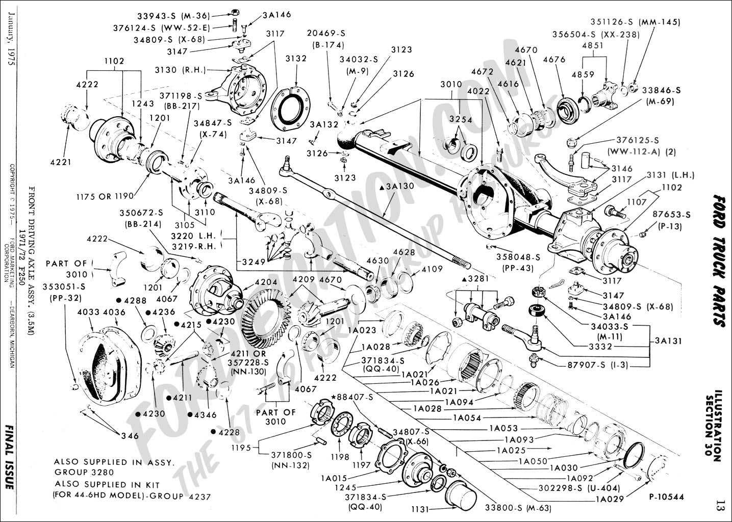
Understanding technical illustrations is crucial for anyone looking to work with vehicle systems. These visual representations provide an overview of how various components interact and their specific placement within the mechanism. By learning to read and interpret these visuals, mechanics and vehicle owners can easily identify parts and understand their functions.
To effectively analyze such a representation, start by recognizing the key symbols and lines that indicate connections between different components. Each part is typically labeled, showing its name and sometimes its specifications. Look for color coding or shading, which may indicate whether the part is operational, requires maintenance, or needs replacement.
Additionally, pay attention to the orientation and positioning of the elements, as they reflect the actual configuration in the vehicle. Understanding these aspects will guide you in locating and diagnosing issues more efficiently, making repairs or replacements straightforward tasks.