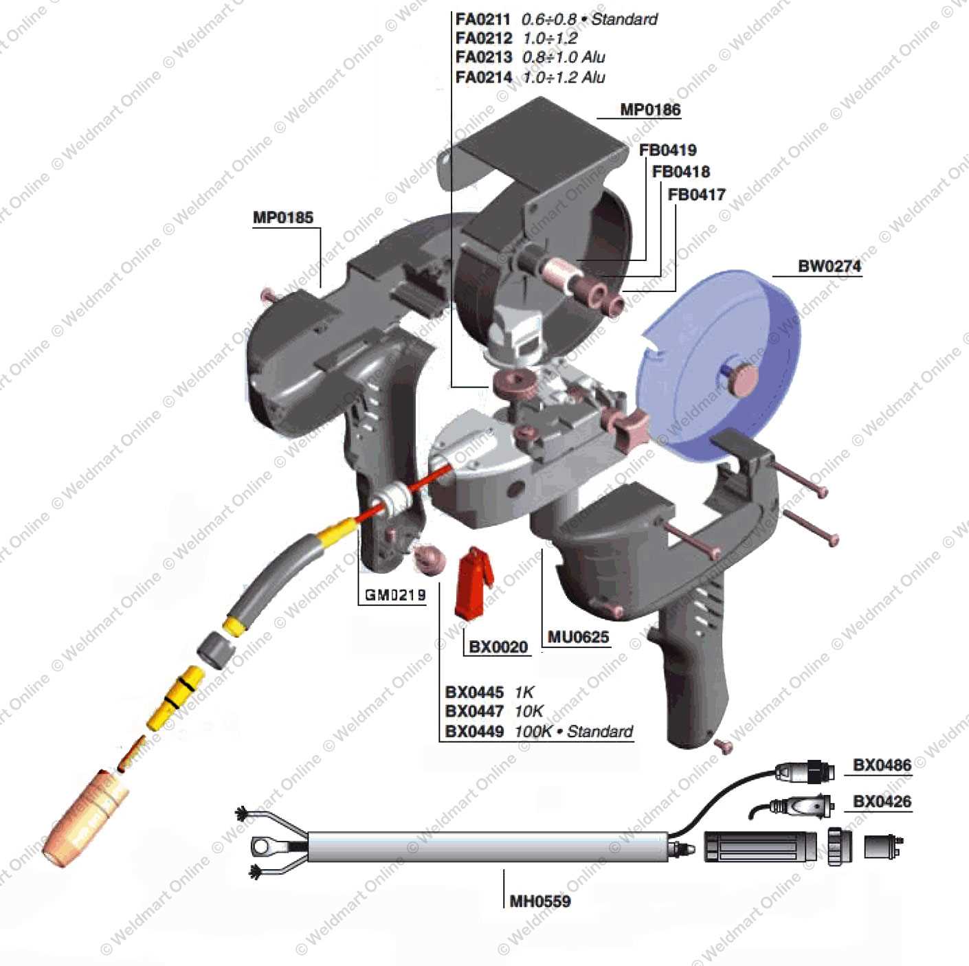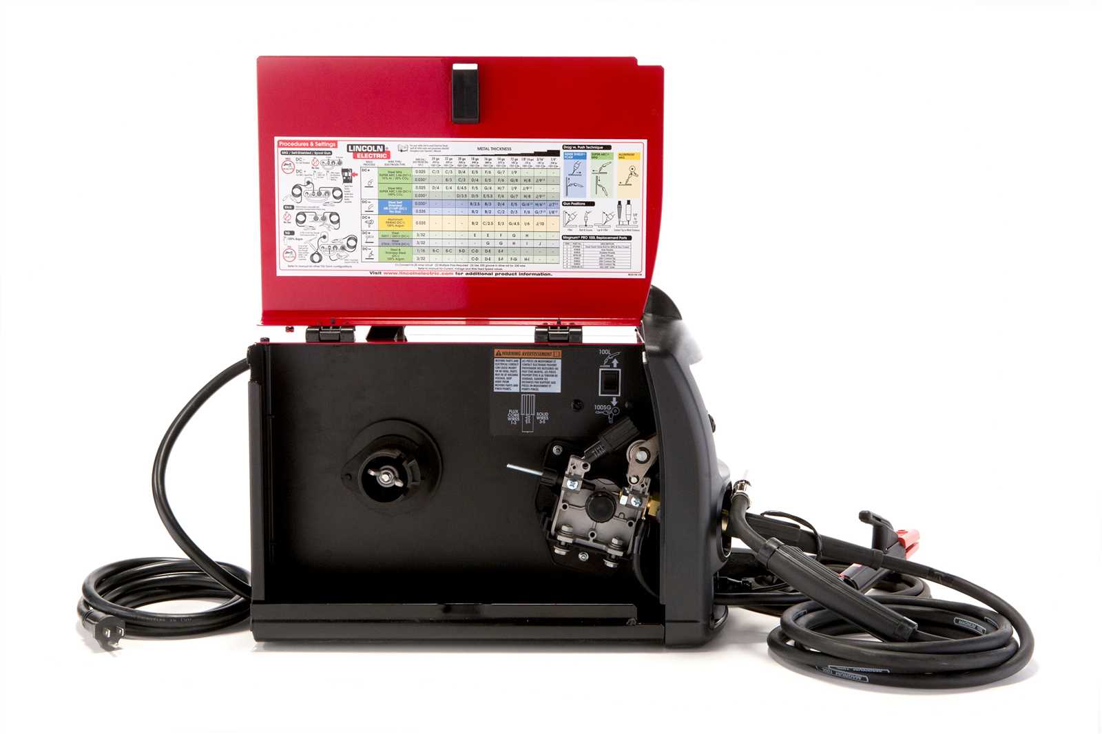
When working with complex machinery, understanding the internal structure and components is essential for proper operation and maintenance. A clear overview of each element allows users to identify and address issues more effectively. This knowledge can also prevent unnecessary repairs and improve the overall lifespan of the equipment.
In this section, we will break down the essential elements of the device, highlighting how each part contributes to the functioning of the system. Whether you are a beginner or an experienced user, mastering the layout and functions of these components will enhance your ability to troubleshoot and maintain the equipment.
Understanding the key features and their roles in the system ensures that you can perform basic repairs or adjustments with confidence. By familiarizing yourself with the various sections and their interconnections, you’ll be better prepared for any issues that arise during use.
Understanding the Equipment Components
Every piece of machinery consists of numerous elements, each playing a vital role in ensuring smooth operation. These components work in unison to create a functional system, and knowing how they interact can help in troubleshooting and repair. Understanding their function allows users to quickly address any issues that may arise during use.
The core elements of the system are designed for specific tasks, such as controlling the flow of power, regulating temperature, or ensuring stability during operation. Familiarizing yourself with the layout and purpose of each component makes it easier to identify potential malfunctions or performance problems.
Whether you are maintaining the equipment or performing a repair, understanding these components will greatly improve your ability to work with the device effectively. It’s important to know how each element contributes to the overall functionality to ensure that all parts are in optimal condition for continuous operation.
Key Components of the Assembly
Each machine consists of critical components that are essential for its operation. These key elements are responsible for various functions, such as controlling power flow, maintaining heat regulation, and ensuring the machine’s structural integrity. A clear understanding of these components helps users operate the equipment more efficiently and safely.
Power Supply and Control Mechanisms
The power supply is a fundamental part of any machine that operates with electrical energy. It provides the necessary voltage and current to drive the system’s processes. Control mechanisms, such as switches and dials, regulate this power, allowing the user to adjust settings according to the task at hand. Proper knowledge of how these elements work together ensures optimal performance and safety.
Cooling and Protection Systems

Another vital aspect of the assembly is the cooling system, which prevents overheating during operation. These systems are designed to maintain the right temperature range for the machine’s components. Alongside cooling, protective elements such as fuses and insulation work to shield the machine from potential damage due to electrical surges or excessive heat.
How to Read the Components Schematic
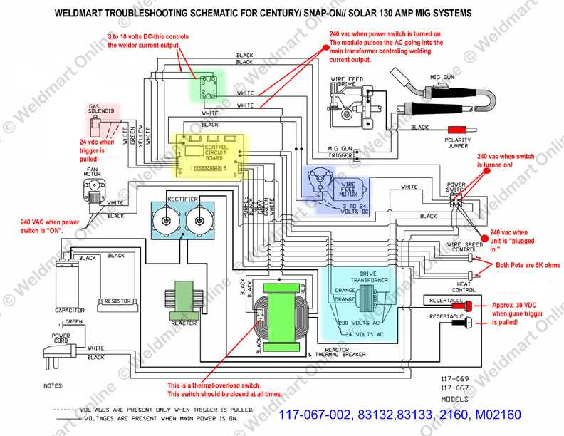
Understanding how to read a schematic is essential for anyone looking to maintain or repair complex machinery. A schematic serves as a visual representation of how various elements are connected and interact within the system. Knowing how to interpret this visual guide helps users quickly locate parts, identify issues, and make informed decisions during maintenance or repairs.
Identifying Symbols and Labels

The first step in reading any schematic is recognizing the different symbols and labels used to represent the components. Each symbol corresponds to a specific part of the system, and these symbols are often accompanied by numbers or letters to further distinguish them. Pay attention to these identifiers as they help pinpoint the exact component being referenced in the guide.
Understanding the Layout and Flow
Once the symbols and labels are clear, the next step is to understand the flow of energy or signals through the system. The schematic typically shows how different elements are connected and how they function together to achieve the desired result. Tracing the flow path helps identify potential problem areas and is crucial when troubleshooting or replacing faulty components.