The machinery used in modern farming relies on precise and efficient connections between components. Understanding these systems is crucial for proper maintenance and optimal performance. Proper assembly and adjustments are key for ensuring that equipment functions as intended during various tasks on the field.
Farming implements require specific mechanical interfaces to be attached to the tractor. These connections allow for stability, flexibility, and ease of use. Familiarity with the layout of these components helps operators identify potential issues and ensure smooth operation. This guide will delve into the essential elements and their roles in these mechanical setups.
Understanding the 3 Point Hitch System

In modern agricultural machinery, the connection between the tractor and various implements is essential for their effective use. These systems ensure that attachments are secured properly and can be easily manipulated. The structure that facilitates this connection plays a vital role in the efficiency of farming operations, enabling the tractor to transfer power and provide stability during tasks.
Functionality of the Connection Mechanism

The core function of this system is to create a stable link between the tractor and the equipment being used. This allows operators to control the implements with precision and adjust them as needed. By ensuring the correct configuration, these mechanisms help achieve maximum performance and reduce wear on both the tractor and the tools being used.
Key Elements of the System
Several key components are involved in this mechanism, each with its own role. These include stabilizing arms, lifting devices, and control mechanisms that allow operators to adjust the height and angle of the attached tools. Understanding these elements is crucial for maintaining the system and preventing operational issues. Proper alignment and functionality are necessary to ensure smooth interaction between the tractor and attachments.
Key Components of a 3 Point Hitch
In agricultural machinery, the system that connects the tractor to its implements relies on several crucial components. These elements ensure that attachments are securely held, while allowing for movement and adjustment during use. Each part serves a specific purpose, contributing to the overall functionality and stability of the setup. Understanding these components is essential for maintaining the equipment and ensuring efficient operation in the field.
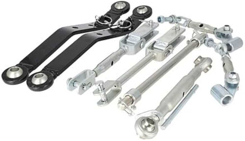
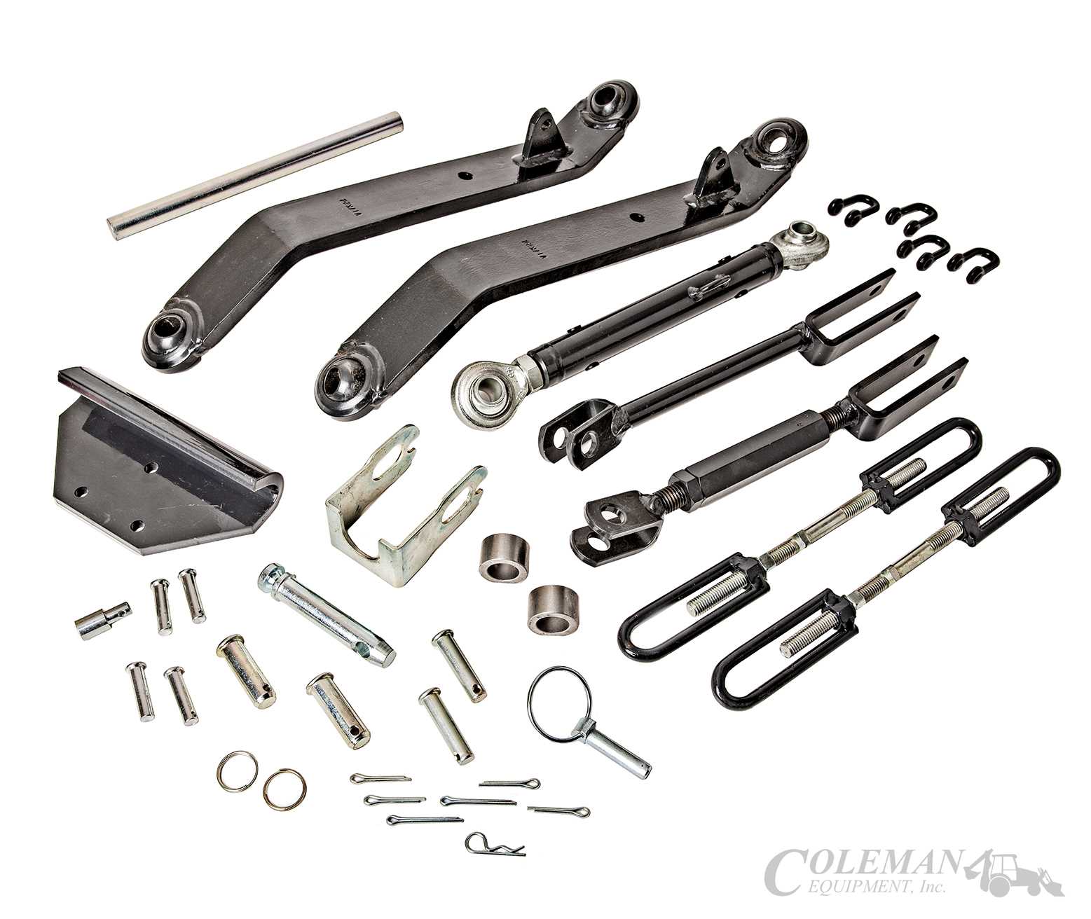
Lift Arms are one of the primary components responsible for raising and lowering attached equipment. These arms provide the necessary support to adjust the height of the implement, ensuring proper ground clearance and optimal performance during various tasks.
Lower Links play a critical role in stabilizing the equipment and ensuring that it remains firmly connected to the tractor. They are adjustable, allowing for precise control over the attachment’s positioning and helping distribute the load evenly during operation.
Top Link helps control the angle and alignment of the implement, providing additional flexibility when adjusting the attachment’s position. It ensures that the equipment functions effectively in different working conditions, contributing to the overall precision of the operation.
How to Interpret a Hitch Parts Diagram
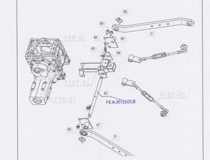
Understanding technical illustrations is key when working with mechanical systems in agriculture. These visuals provide a clear representation of the components, their layout, and how they interact with each other. By learning how to read these diagrams, operators can identify parts, troubleshoot issues, and ensure everything is connected correctly for smooth operation.
Identifying Key Elements
The first step in interpreting these visuals is to identify the main components represented. These illustrations typically show the different elements such as the lifting mechanism, stabilizing arms, and adjustable links. By understanding what each symbol or line represents, users can get a clearer understanding of the setup and how each part functions within the system.
Reading Labels and Measurements
Diagrams often include labels and measurements to provide precise details about each component’s size, alignment, and connection points. Paying attention to these specifics is crucial, as they help users to correctly assemble, maintain, or replace parts. These measurements ensure that everything fits properly and operates effectively, preventing potential issues in the field.