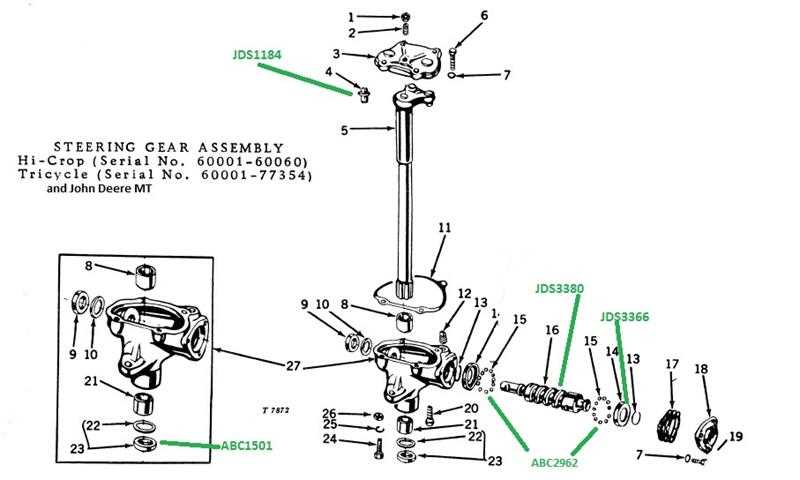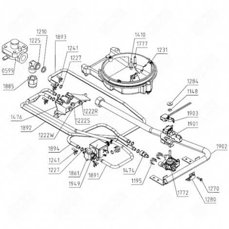
Understanding the inner workings of a lawnmower or small tractor is essential for both maintenance and efficient operation. With detailed illustrations of key mechanical elements, it’s possible to recognize each component’s role and how they contribute to the overall functionality. Proper knowledge can significantly reduce repair costs and increase the longevity of the machine.
Exploring the structure of these systems can be overwhelming without the right visual aids. The provided illustrations break down complex assemblies into manageable sections, helping owners and technicians alike identify necessary parts for repairs or replacements. This understanding empowers users to keep their machines running smoothly for years.
Regular maintenance and an informed approach to repairs ensure that the machinery operates at its peak efficiency. With a clear understanding of each part’s purpose, one can perform the necessary upkeep without unnecessary delays or confusion. Whether you’re a first-time user or an experienced technician, the detailed breakdown is an invaluable tool for anyone working with such machines.
Understanding the Tractor Mechanical System

Every mechanical system in a lawnmower or small agricultural vehicle plays a crucial role in its overall performance. Understanding how these systems interact allows users to properly maintain and troubleshoot the machine. Key components such as the drive assembly, cooling system, and fuel management all work together to ensure the equipment runs efficiently.
Familiarity with the structure and function of these systems not only helps identify common issues but also aids in the selection of suitable replacement components. When something goes wrong, knowing the machine’s layout and the purpose of each part helps in diagnosing the issue more accurately, leading to faster and more cost-effective solutions.
Additionally, recognizing the interconnectivity of each part allows for better preventive care, ensuring that wear and tear does not lead to bigger, more expensive problems. By understanding the basics of the machine’s design, operators can avoid many common pitfalls and extend the life of their equipment.
Key Components in the System Layout

The functionality of any small vehicle or lawnmower relies heavily on its core components. A clear understanding of these elements helps operators troubleshoot and perform necessary maintenance tasks. Below are the essential parts that make up the internal structure of these machines:
- Power Transmission: The mechanism that transfers the engine’s power to the wheels, ensuring movement and control.
- Fuel System: This system manages the delivery of fuel to the combustion chamber, crucial for engine operation.
- Cooling System: Keeps the engine temperature in check to prevent overheating and maintain optimal performance.
- Ignition System: Responsible for starting the engine and keeping it running smoothly by creating the spark needed for combustion.
- Lubrication System: Ensures that moving parts are properly lubricated to reduce wear and increase efficiency.
Each component plays a vital role, and without any of them functioning properly, the machine’s performance would be compromised. Understanding these key parts ensures smoother operation and reduces the likelihood of major malfunctions.
How to Use the System Layout for Repairs

When performing repairs on a mechanical system, having a clear reference of its components can make the process much more efficient. A well-detailed visual guide helps in identifying the location of each part, ensuring that you can easily locate the areas that need attention. This reference is especially useful for diagnosing issues and determining the necessary replacements or fixes.
To begin, closely examine the layout to understand how the various components are connected. Identify any broken, worn, or faulty parts that require immediate attention. Once the problematic part is located, the guide can also assist in finding the part’s specification and model number, ensuring you purchase the correct replacement.
Additionally, a visual reference simplifies the reassembly process. As you replace or repair individual components, use the guide to ensure everything is correctly aligned and reconnected. By following the visual aid step-by-step, you’ll avoid common errors and reduce the chances of leaving parts loose or incorrectly installed.