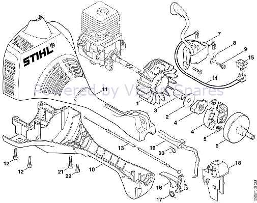
When it comes to maintaining outdoor equipment, knowing how its individual elements fit together is crucial. A clear layout of its internal and external sections helps you identify parts quickly and ensures smooth functioning.
Familiarizing yourself with the structure allows you to perform better repairs and troubleshoot issues with ease. Understanding how components interact can also prevent costly mistakes during disassembly or assembly.
Having the right visual guide can significantly simplify this process, providing clarity when replacing or inspecting parts. Whether you’re a beginner or an experienced user, the ability to decode these representations will help you keep your equipment in top shape.
Understanding FS 45 Components
In any mechanical device, a clear understanding of its core elements is essential for effective operation and maintenance. The components that make up the system work together, and knowing their function and placement can help you troubleshoot or replace them when needed. This section will provide an overview of the key sections and pieces that form the structure of the FS 45, allowing for better comprehension and easier repairs.
Key Sections of the Equipment
The equipment consists of various crucial sections, each with a specific role in ensuring smooth performance. From the engine to the housing, these parts are designed to withstand various tasks. Understanding how they contribute to the overall functionality of the system is vital for anyone looking to maintain or repair the device effectively.
Commonly Replaced Elements
Over time, some components are more likely to need replacement due to wear and tear. Familiarizing yourself with these parts and their locations helps in planning maintenance tasks. Whether it’s the cutting mechanism or the engine components, knowing which parts are often replaced will save you time and effort.
How to Read the Component Layout
Decoding a visual representation of a device can greatly simplify maintenance and repair tasks. Understanding how to read and interpret these images is crucial for identifying individual elements and their arrangement. This section will guide you through the essential steps to effectively analyze a layout, allowing you to find the right pieces quickly and accurately.
Breaking Down the Symbols
Most visual guides use specific symbols to represent each section of the device. Familiarizing yourself with these symbols and their meaning is the first step to understanding how the parts are connected. Each symbol typically corresponds to a distinct part, and learning what each one signifies will give you a clear idea of the device’s structure.
Identifying Key Components
Once you’re familiar with the symbols, focus on identifying the most important sections of the layout. These may include the motor, cutting mechanism, or housing. Recognizing these primary areas helps you focus on the critical parts first, making repairs or replacements much easier and more efficient.
Essential Tools for FS 45 Repairs
To perform effective repairs and maintenance, having the right tools is essential. Each task, whether it’s a simple fix or a complex assembly, requires specific equipment to ensure everything is done properly. This section outlines the must-have tools you’ll need to handle repairs and keep your device in top condition.
Basic Tools for Routine Maintenance
For everyday maintenance tasks, a few basic tools can go a long way in ensuring smooth operation. Here are the most commonly used tools:
- Screwdrivers: Both flathead and Phillips screwdrivers are essential for loosening and tightening screws.
- Wrenches: Adjustable and socket wrenches are necessary for securing bolts and nuts.
- Pliers: Useful for gripping and pulling components when needed.
- Cleaning Brushes: Keeping parts clean is vital, and brushes help remove debris and dirt effectively.
Advanced Tools for In-Depth Repairs
For more complex repairs, such as engine adjustments or major component replacements, advanced tools will be required:
- Torque Wrench: Ensures bolts are tightened to the manufacturer’s specified torque, preventing damage.
- Compression Tester: Used to check the engine’s compression levels and diagnose potential issues.
- Feeler Gauge: Helps in adjusting clearances between parts for precise operation.
- Parts Puller: Ideal for removing stuck components without causing damage.