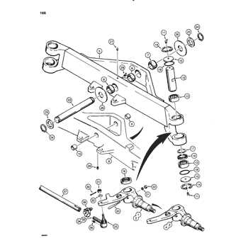
For those working with heavy machinery, having a clear understanding of the different components and how they fit together is crucial. Knowing the layout of various parts can make maintenance and repair tasks much easier and faster. This guide aims to break down the essential elements needed to properly manage and service your equipment.
Illustrating the structure of the machine is an essential step in any repair or maintenance process. By understanding each part’s location and function, you can address issues with confidence and accuracy. Whether you are dealing with common wear and tear or more complex repairs, this knowledge is invaluable for efficient troubleshooting.
With the right resources, any user can develop the skills necessary to work effectively with their machinery. This article will help you navigate through the key details to ensure your equipment operates at its best, avoiding unnecessary breakdowns and enhancing performance.
Understanding the Equipment Components
When working with complex machinery, understanding the individual elements that make up the system is essential for proper maintenance and repair. Each component plays a specific role in the overall function of the equipment, and recognizing their relationships can help in diagnosing issues and ensuring smooth operations. A clear grasp of the equipment’s structure makes troubleshooting and preventive measures more efficient and effective.
Key Elements of the Machine
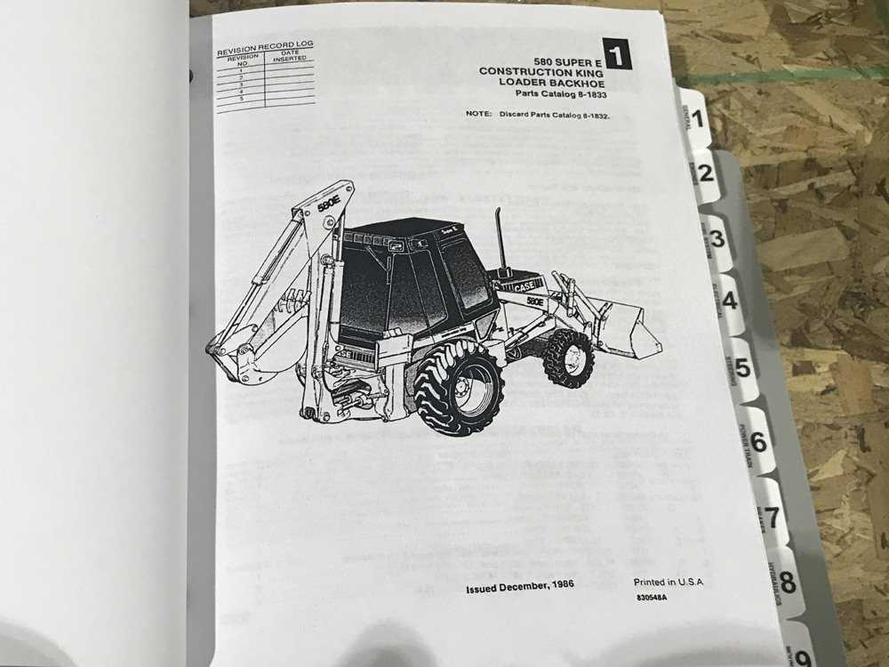
The machine consists of several crucial sections, each designed to perform a specific function. From the engine to the hydraulic systems, each part is interlinked and contributes to the overall performance. Recognizing how these components work together is vital for identifying potential problems and addressing them quickly. The understanding of these elements also aids in ensuring the machine runs at optimal efficiency, reducing downtime and extending its service life.
Maintenance and Repair Considerations
Effective maintenance requires an awareness of the parts that need regular attention and the common wear points. Knowing the specific areas prone to failure can guide technicians in performing proactive repairs. Understanding how to access, replace, or repair these components based on their function within the system is key for keeping the equipment in top condition.
How to Read the Equipment Layout Effectively
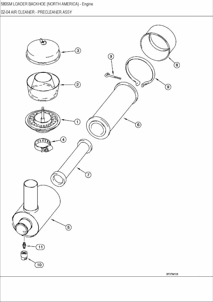
Understanding the layout of a machine is crucial for performing accurate repairs and maintenance. These visual representations offer a clear map of the system, showing how various components are connected and interact with each other. A well-organized schematic can save time and reduce mistakes, as it highlights key areas to focus on during any service procedure.
To read the layout effectively, start by identifying the different sections and their corresponding labels. The diagram typically divides the machine into functional groups, such as the engine, hydraulic systems, and electrical components. Pay close attention to the symbols used, as they often represent specific parts or mechanisms, and make sure to refer to the legend for clarification on any unfamiliar icons.
Once familiar with the general structure, locate the part in question and trace its connections to other components. This will help in understanding how the part functions within the broader system and identify potential problem areas. Using these visual guides in combination with technical manuals can significantly improve troubleshooting efficiency and repair accuracy.
Common Repairs Using the Equipment Layout
Routine maintenance and repairs are essential to keep heavy machinery in good working condition. Understanding the visual representation of a machine’s layout is crucial for identifying which components need attention and how to address common issues. By following a schematic, technicians can save time and ensure repairs are done correctly, reducing the likelihood of future breakdowns.
Engine and Hydraulic System Troubleshooting
Engine issues are one of the most common problems faced by operators. Using the layout, it’s possible to pinpoint specific parts of the engine that may need repair or replacement, such as fuel pumps, filters, or belts. Likewise, the hydraulic system can often experience leaks or failures in hoses, seals, or pumps. The schematic helps identify these components quickly, facilitating more efficient repairs and minimizing downtime.
Electrical and Control System Maintenance
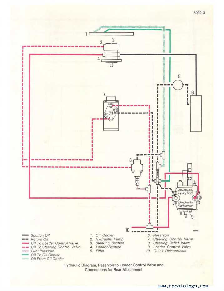
Electrical malfunctions can be particularly challenging to address without a clear overview of the machine’s wiring and control systems. The layout provides a clear guide to trace connections between key electrical parts, such as the alternator, battery, and sensors. Identifying issues such as loose connections or faulty wiring can help restore functionality swiftly, ensuring the equipment operates as expected.