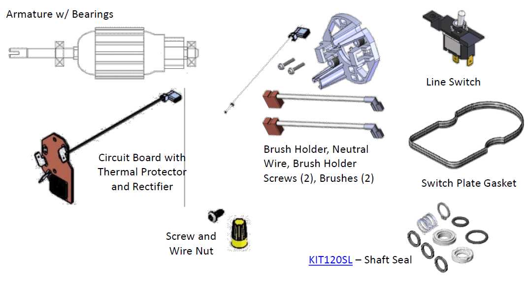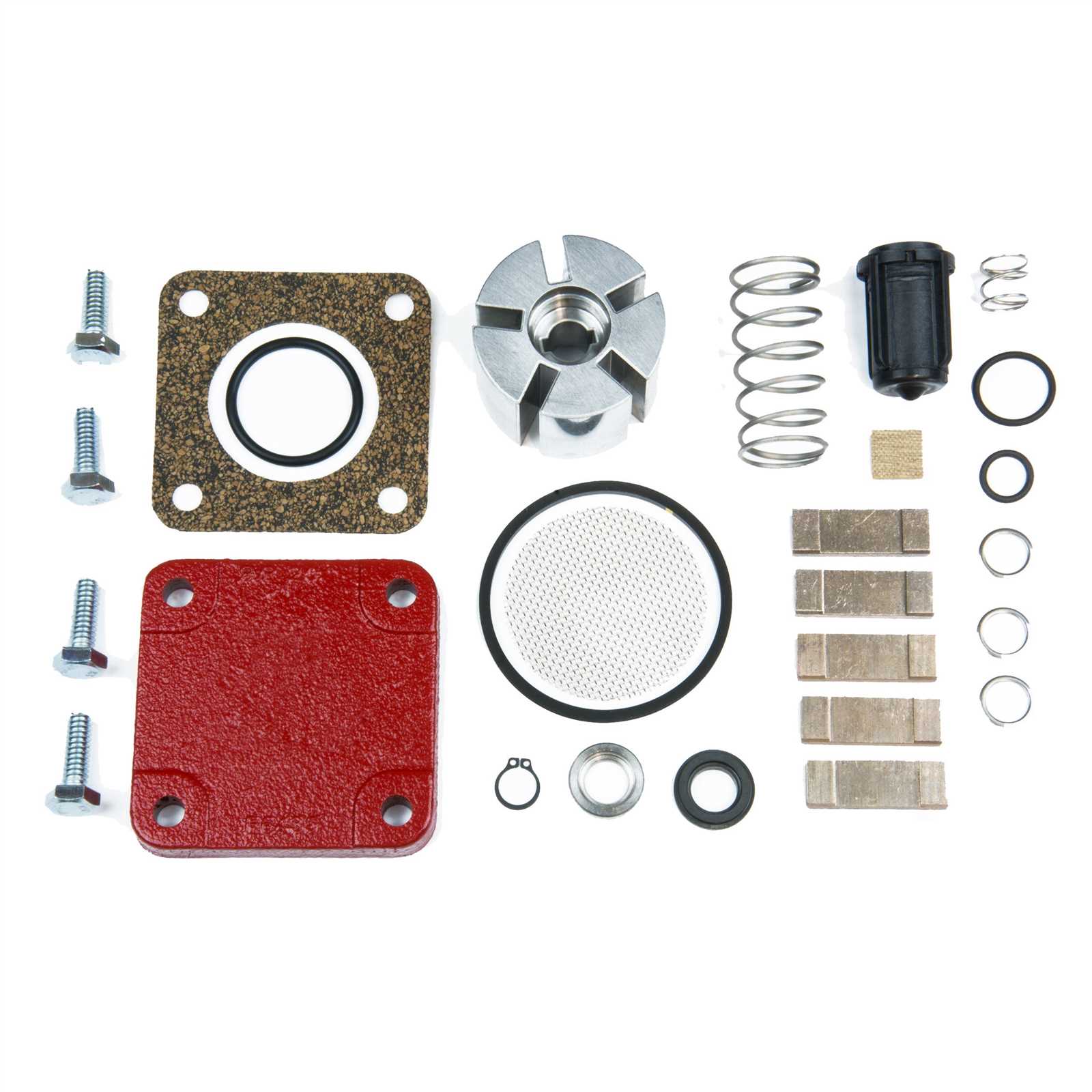
Maintaining the functionality of fueling equipment requires a thorough understanding of its internal components and their relationships. Whether you are handling repairs or routine checks, knowing the structure and assembly of each part is essential for efficiency and safety.
The internal mechanisms of a fueling device are often complex, with various elements working together. By studying the layout and connections of these parts, you can diagnose issues more effectively and ensure the system operates smoothly. Familiarity with each component helps identify wear and tear, as well as potential failures before they become major problems.
Understanding how to interpret these mechanical systems will allow operators and technicians to troubleshoot with confidence. Proper knowledge enables timely interventions, reduces operational downtime, and extends the lifespan of the equipment.
Understanding Fueling Equipment Components

To effectively manage and maintain fueling systems, it is crucial to comprehend the internal mechanisms that drive their operation. Each system consists of various interconnected elements, each playing a vital role in overall performance and reliability. Gaining insight into how these parts function together ensures better handling and troubleshooting when issues arise.
Key Functional Elements
The core components of the equipment include the motor, hoses, filters, and valves. Each of these elements contributes to the smooth transfer and control of fuel. The motor powers the system, while the hoses transport the liquid to the desired destination. Filters ensure the fuel remains free of contaminants, and valves regulate the flow and pressure, preventing potential damage.
Interconnections and Assembly
Understanding how each element interacts with the others is vital for diagnosing and repairing the system. For instance, a malfunction in one part can often affect the performance of others. Knowledge of the assembly and arrangement of these elements allows technicians to quickly locate the source of any issue and perform the necessary fixes without unnecessary delays.
How to Read Fueling System Schematic
Interpreting the schematic of any fueling equipment requires a clear understanding of the symbols, labels, and connections represented. These visual guides offer a detailed map of the system, highlighting the relationships between different elements. By studying the layout, you can identify each component’s function and troubleshoot potential issues effectively.
Symbols and Labels
In most schematics, specific symbols represent different components, such as the motor, valves, and filtration units. These symbols help you quickly recognize each part’s role within the system. Understanding these symbols is key to interpreting the flow and layout correctly, allowing you to understand how the system operates.
Connections and Flow
The connections between components are just as important as the parts themselves. Examining the flow paths will give you insight into how the system functions as a whole. This includes understanding the direction of fluid movement, pressure points, and potential areas where blockages or malfunctions could occur.
Common Issues with Fueling System Components
In any fueling system, certain components are more prone to wear and tear, leading to common issues that can affect overall performance. Recognizing these problems early can help prevent costly repairs and ensure smooth operation. Regular maintenance and awareness of potential faults are key to avoiding major disruptions.
One frequent issue involves clogging of filters or hoses, which can reduce fuel flow or cause uneven dispensing. This is often caused by dirt or debris, making it essential to clean and replace these elements regularly. Additionally, valve malfunctions are another common concern. If the valves become stuck or fail to open or close properly, it can lead to fuel leaks or pressure irregularities.
Another issue is wear on the motor or electrical components, which can result in failure to start or intermittent operation. Proper lubrication and timely inspections of the motor are crucial for preventing this. Finally, leaks in any of the connections or seals can lead to safety hazards and loss of fuel, requiring immediate attention.