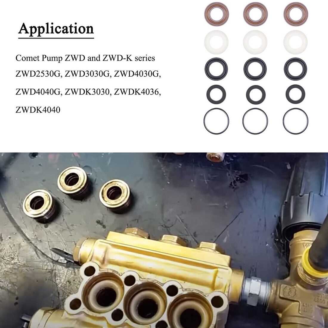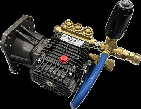
Having a clear overview of the components and their arrangement in machinery is crucial for efficient maintenance and troubleshooting. This section provides a detailed visual representation to help users identify various parts and their functions, enabling them to perform necessary repairs and replacements.
By following the provided visual guide, users can gain a better understanding of the device’s structure. The accurate identification of each element is essential for ensuring the machine operates smoothly and efficiently over time. With this knowledge, users will be better prepared for common issues and basic maintenance tasks.
Understanding the layout of each part can also prevent costly mistakes and enhance the lifespan of the equipment. Whether you’re dealing with a malfunction or simply aiming to maintain peak performance, a proper grasp of the system’s structure is key to achieving successful outcomes.
Understanding the Components of the Device
To maintain and repair a complex machine, it’s essential to understand its individual components and how they interact. Identifying each element within the system ensures that users can address potential issues promptly and efficiently. Proper knowledge of the device’s structure is the first step toward effective operation and troubleshooting.
Key Elements and Their Functions

Each component in the system plays a specific role, contributing to the overall functionality. From the power source to smaller functional elements, recognizing their purpose allows for quick identification of malfunctions. Understanding their arrangement aids in improving both performance and longevity.
Common Challenges and Solutions
Familiarity with the components also helps users recognize common issues. Knowing how parts are connected can prevent mistakes during repairs and maintenance. With this insight, users are better prepared to address typical problems, saving time and avoiding unnecessary disruptions.
How to Read the Visual Guide
Understanding how to interpret a technical illustration is essential for performing accurate maintenance or repairs. These visual aids are designed to provide clear information about the structure and connection of each component within the system. By learning how to read these guides, users can ensure they handle each part correctly and identify areas that need attention.
The key to reading these illustrations lies in recognizing the symbols and labels that correspond to specific elements of the device. Each part is typically numbered or marked, and understanding these references allows users to match them with the physical components. It’s important to familiarize yourself with the layout so that you can efficiently follow the instructions when performing repairs or upgrades.
Common Issues and Solutions for Components
Understanding the typical problems that can arise with various elements of a system is essential for quick and effective troubleshooting. When issues occur, knowing the most likely causes and their solutions can save time and prevent further damage. This section explores common challenges faced with key components and offers practical solutions to address them.
Wear and Tear of Key Elements
Over time, certain components may experience wear due to frequent use, leading to reduced efficiency or malfunction. Regular inspection of these elements can help identify signs of wear early. Replacing damaged or worn parts with high-quality replacements can restore proper functioning and extend the lifespan of the system.
Connection and Alignment Issues
Misalignments or loose connections can often cause operational failures. Ensuring that all components are properly aligned and securely connected can resolve many issues. Tightening loose fasteners or adjusting misaligned parts can improve the overall performance of the system and prevent future disruptions.