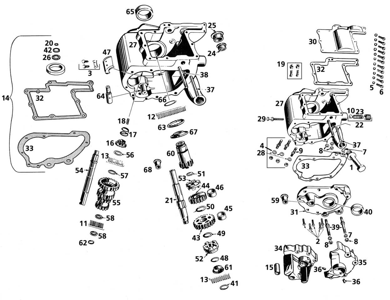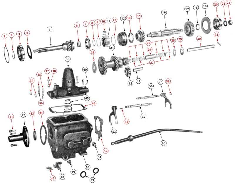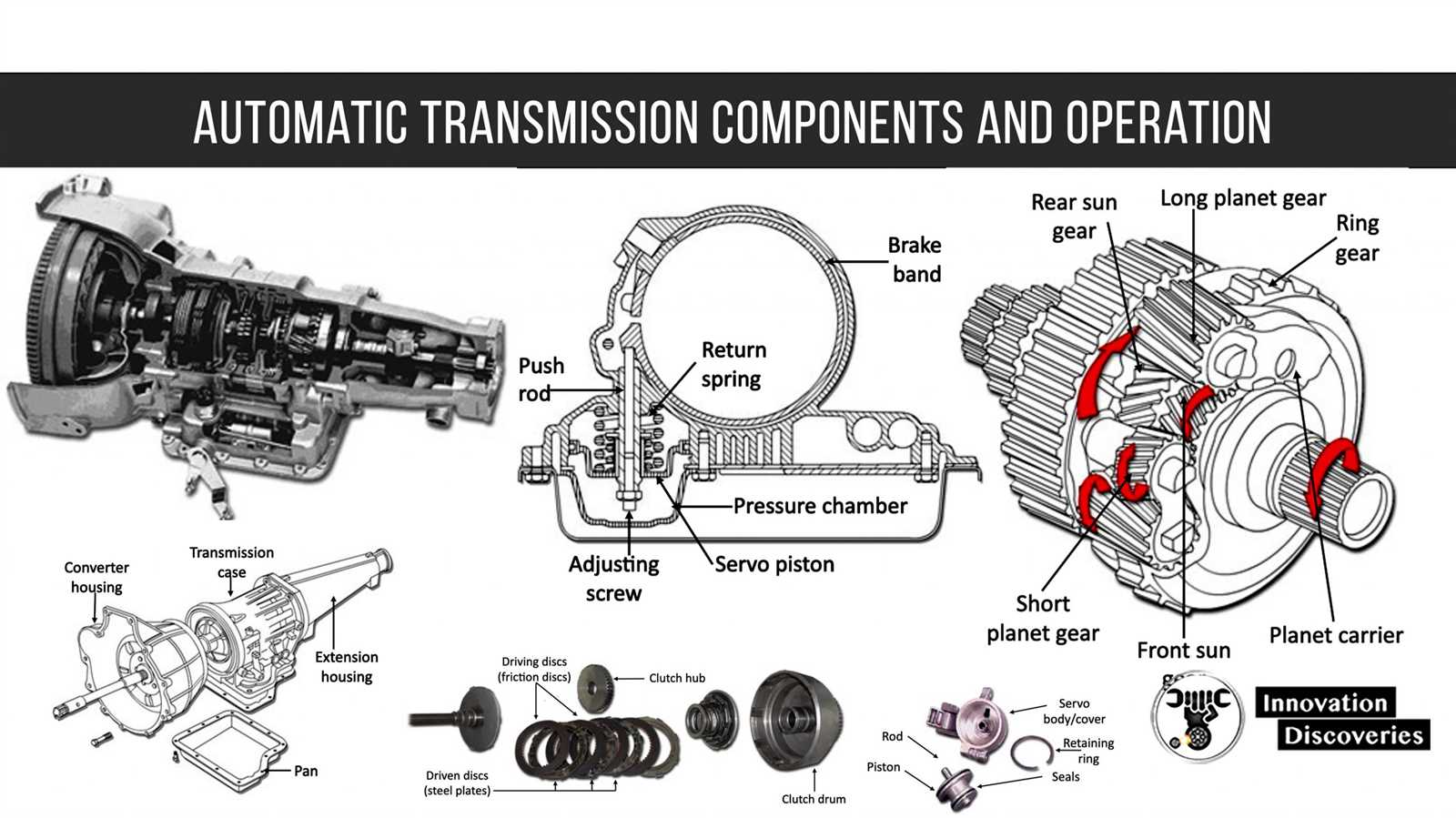
In the study of mechanical and electrical systems, schematics play a crucial role in depicting how components interact within a given setup. These visual representations provide valuable insights into the functionality and structure of complex systems, enabling engineers and technicians to analyze and troubleshoot more efficiently.
Key components in these visual layouts are essential for ensuring that the system operates as intended. Each element has a specific function, contributing to the overall design and efficiency of the system. Without a clear understanding of how these parts relate to each other, it becomes challenging to optimize performance or resolve issues.
From mechanical linkages to electrical connections, the way these components are depicted can greatly impact the ease of understanding and problem-solving. It is important to break down these visuals into their fundamental units to understand their individual roles and how they work together. This breakdown can lead to better troubleshooting, improved designs, and more efficient maintenance of systems in various industries.
Essential Components of Transmission Diagrams
When examining the workings of complex mechanical or electrical systems, it’s essential to understand the fundamental elements that make up visual representations of their structure. These components serve as the building blocks, offering clarity and insight into the interrelations between different system parts. Each element is carefully placed to showcase how energy, force, or information flows throughout the system, allowing for better design, analysis, and maintenance.
Key Elements in Visual Layouts
The primary elements in these schematics include mechanical linkages, electrical connectors, and control units. These key elements show how different system components are connected and interact with each other. In many cases, lines or arrows are used to represent the flow of energy or data, helping to visualize the complex relationships between different units. Understanding these visual cues is critical for anyone involved in designing or repairing these systems.
The Role of Connectors and Nodes

Connectors and nodes play a crucial role in defining the points of interaction within a system. These components represent specific locations where signals or energy are transmitted or received. Nodes often serve as junctions for various parts, where changes in flow, pressure, or voltage occur. By studying these connection points, engineers can identify potential weaknesses or areas for improvement in system design.
How Transmission Diagrams Work in Systems

In any system, visual representations are essential for illustrating how components interact and work together to achieve a common goal. These representations help identify how energy, information, or forces flow from one element to another, providing clarity in complex setups. They offer a map of the entire system, highlighting critical connections and the sequence of operations required for optimal performance.
Through clear visual cues, these schematics make it easier for engineers and technicians to identify how various elements are connected and how their functions influence each other. The lines, symbols, and annotations on these layouts allow for quick identification of key system pathways, ensuring that any adjustments or repairs can be made efficiently.
Understanding the flow of energy or information in these systems is crucial. For example, when energy travels through specific channels, it might pass through different control units or be converted into other forms of energy. Recognizing these processes visually makes troubleshooting and optimization much more manageable, ensuring that systems are operating at their peak efficiency.
Applications of Transmission Diagrams in Engineering
In engineering, visual schematics serve as essential tools for designing, analyzing, and maintaining complex systems. These representations are used across various fields to optimize the interaction of components and ensure smooth operation. Engineers rely on them to streamline processes, reduce errors, and enhance efficiency by providing a clear view of how each element contributes to the system as a whole.
One key application is in the design phase, where schematics are created to plan the integration of various system components. By visually mapping out connections, engineers can easily identify potential design flaws or areas for improvement before physical construction begins. This allows for faster and more cost-effective development, as potential issues are addressed early on.
Another important use is in maintenance and troubleshooting. When systems experience issues, having a clear layout of their components helps technicians quickly identify where the problem might lie. These visuals act as a guide to pinpoint faulty connections or malfunctioning units, enabling quicker repairs and minimizing downtime in industrial applications.