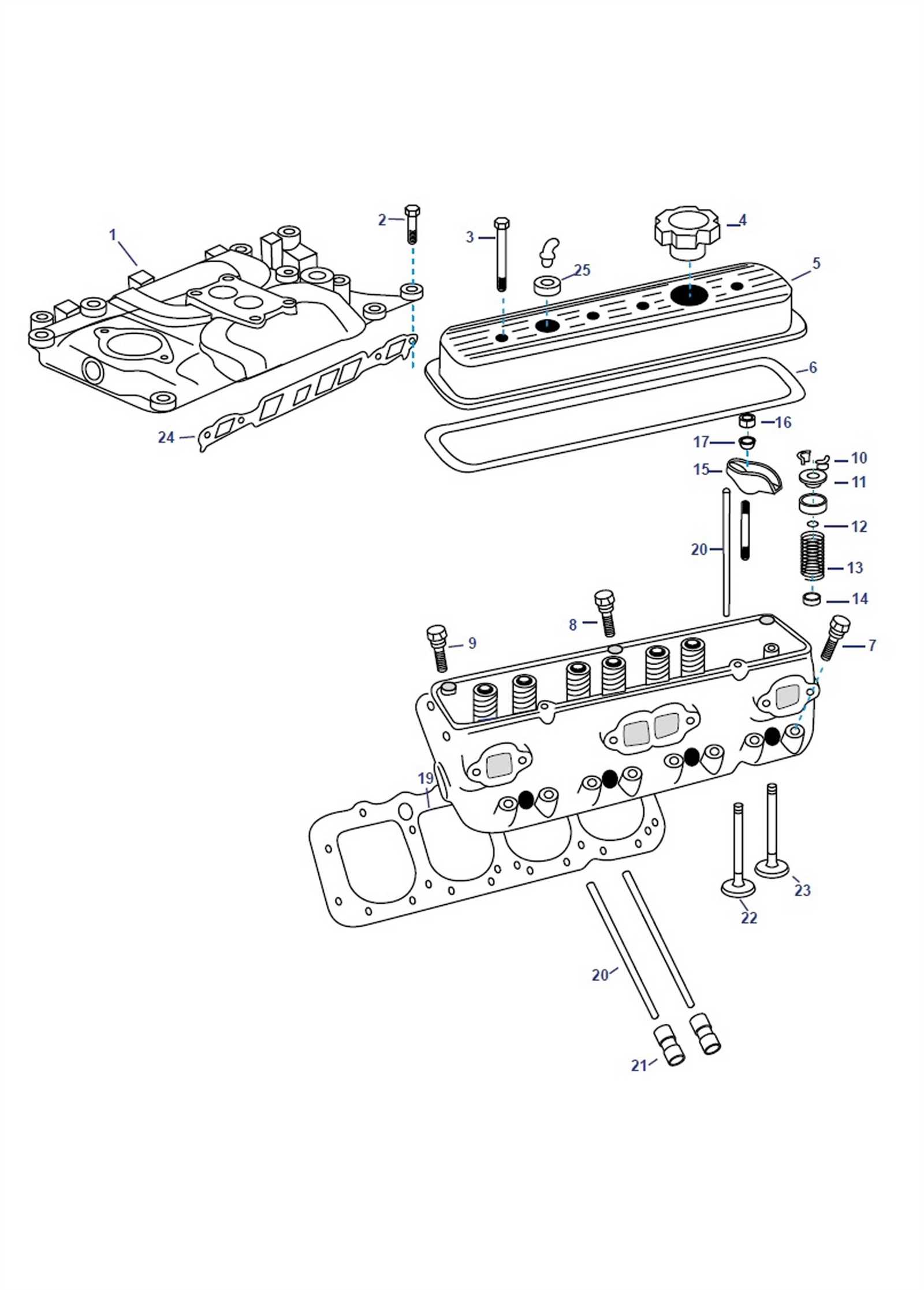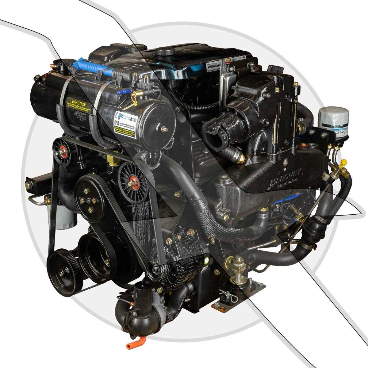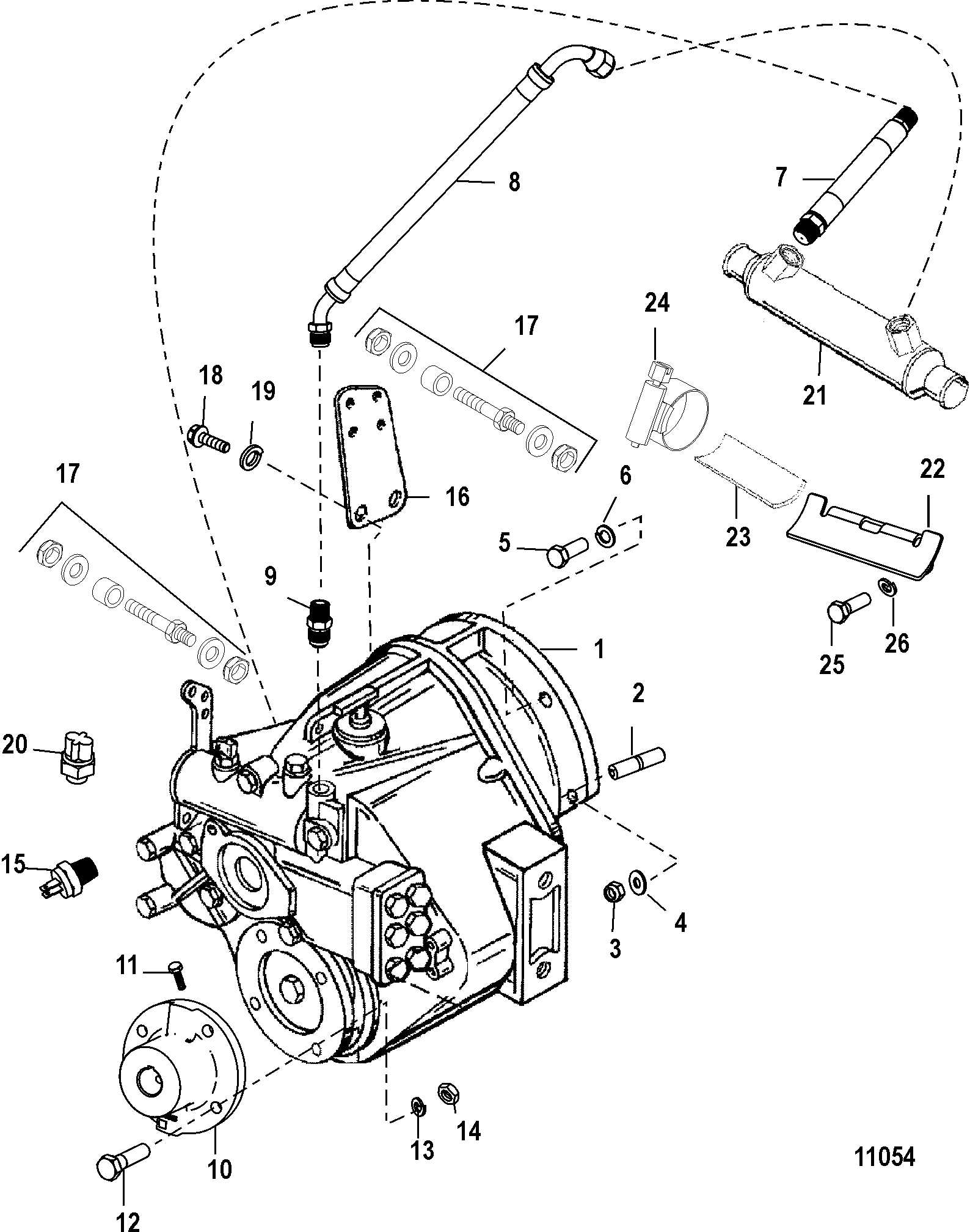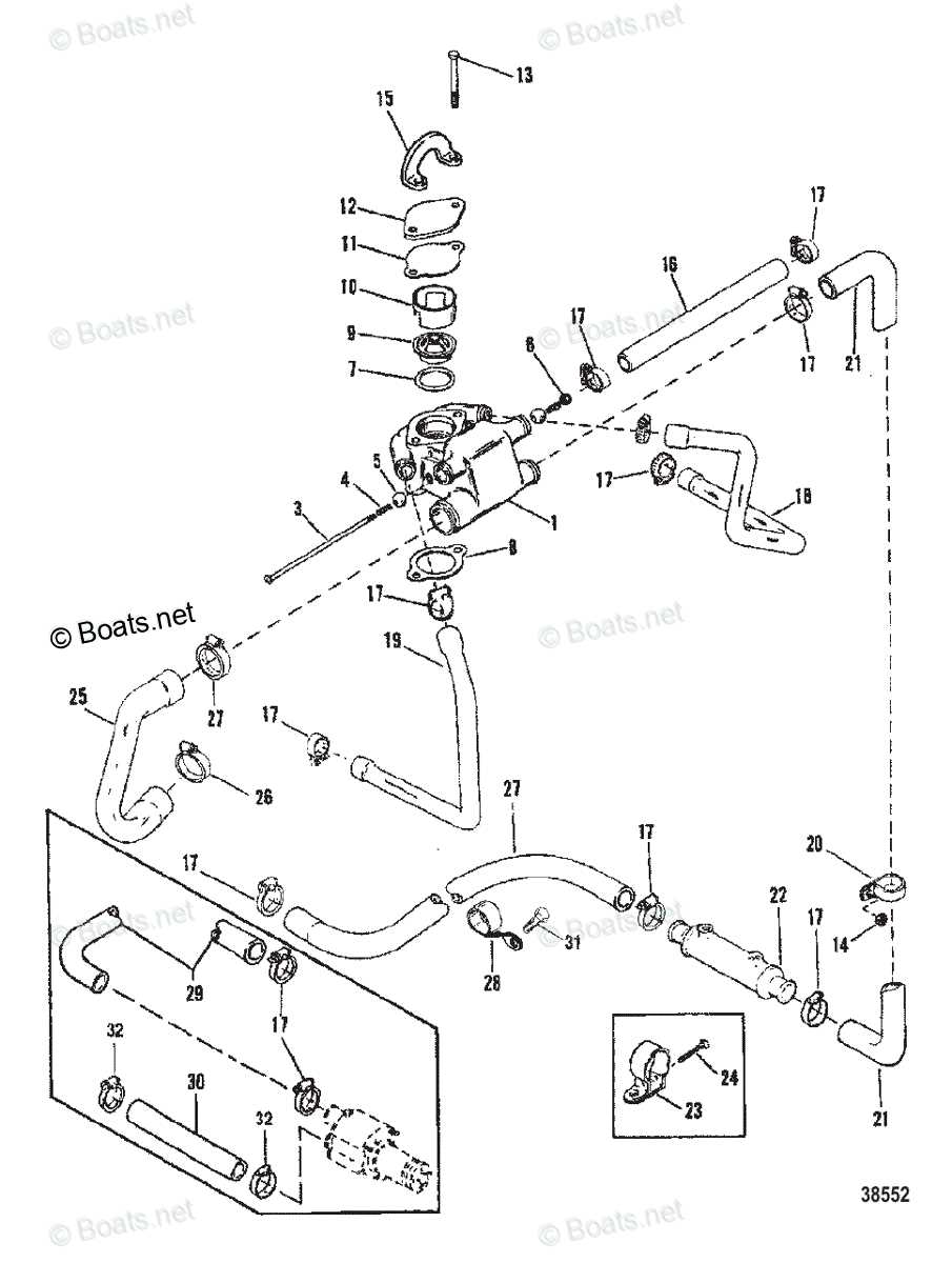
Having a clear understanding of an engine’s structure is essential for proper maintenance and repairs. Knowing how the different elements interact ensures smoother operation and reduces the risk of malfunction. This guide provides a detailed look at the various sections that make up the system, highlighting their specific roles and functions.
Whether you’re a seasoned technician or a beginner, familiarity with the layout of engine parts can significantly simplify troubleshooting. With the right knowledge, identifying issues and carrying out replacements or repairs becomes more efficient and less time-consuming.
Accurate identification of parts plays a crucial role in ensuring compatibility and longevity. By referencing comprehensive diagrams, users can gain insight into the arrangement and connections of key components, making maintenance tasks more manageable.
Understanding the Engine Components
Properly understanding the various components of an engine is vital for effective maintenance and repairs. Each part plays a crucial role in the overall function, and knowing their interactions allows for better diagnostics and problem-solving. This section will explore the key elements, focusing on their specific responsibilities and how they contribute to the performance of the system.
The engine’s core assembly consists of multiple interconnected parts that work together to generate power and ensure smooth operation. Identifying each component’s role helps technicians understand how the system operates as a whole, facilitating troubleshooting and preventing potential failures.
From the fuel delivery system to the cooling components, each section serves a unique purpose. For instance, the valve train ensures efficient air intake and exhaust, while the crankshaft plays a key role in transforming fuel energy into mechanical power. Knowing these connections helps improve the overall efficiency and reliability of the engine.
Key Components in the Engine Layout
The engine consists of several crucial elements that work together to ensure smooth and efficient performance. Each of these components is designed to handle specific tasks, and understanding their roles is vital for maintaining and troubleshooting the system. This section outlines the key components that contribute to the engine’s overall functionality and their interaction within the system.
Fuel and Air Delivery System

The fuel and air delivery system ensures that the engine receives the right mixture of fuel and air for optimal combustion. This includes components such as the fuel injectors, throttle body, and intake manifold, which control the flow of air and fuel into the combustion chambers. Proper function of this system is crucial for engine performance and fuel efficiency.
Power Generation and Transmission

The power generation system is primarily responsible for converting energy into mechanical force. Key components in this process include the crankshaft, which transforms the movement of pistons into rotational motion, and the camshaft, which controls the timing of valve operations. These elements work in sync to ensure that power is delivered smoothly to the transmission system for further distribution to the drive shaft.
How to Use the Engine Component Layout

Understanding how to navigate and interpret an engine layout is essential for any technician or enthusiast. A comprehensive layout can provide a clear visual representation of the various components and their connections. Knowing how to read this information allows for quick identification of potential issues and simplifies the process of repairs or replacements.
When examining the layout, start by familiarizing yourself with the overall structure, identifying the main sections such as the fuel system, ignition system, and power transmission. Once you have a general understanding, focus on the individual components, paying attention to their placement and interconnectivity. This will help you identify any parts that may need attention or replacement during maintenance.
By referencing the layout during diagnostics, you can follow the flow of energy and air throughout the system. This helps pinpoint areas where issues might arise, whether in the intake system, exhaust, or power generation components. Understanding the layout not only improves troubleshooting efficiency but also aids in ensuring compatibility when replacing or upgrading parts.