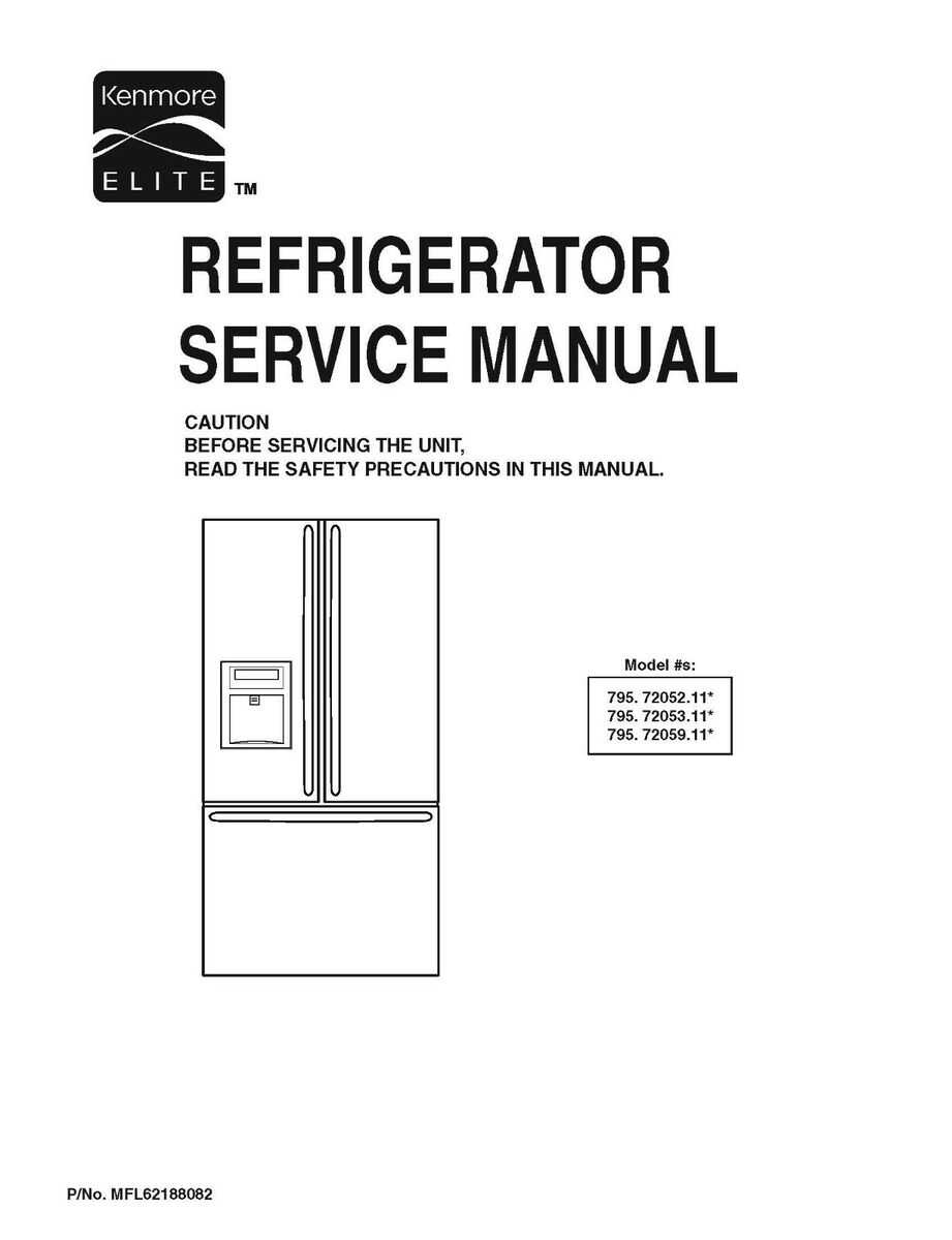
Maintaining and repairing household appliances requires a clear understanding of their internal structure. Having a visual reference of all the key elements can significantly simplify the process. Identifying each component allows for quick diagnostics and proper handling during maintenance tasks.
Visual aids play a crucial role in this process, providing a clear guide to the connections and interactions of different parts. Whether you are troubleshooting or performing regular maintenance, knowing where each piece fits can save both time and effort.
By gaining familiarity with these detailed illustrations, owners can enhance their ability to repair malfunctioning units effectively. Understanding these layouts is an essential skill for anyone aiming to maintain their appliances in peak condition.
Understanding Appliance Components
Every household machine is made up of a variety of interconnected components that work together to perform its functions. Understanding how each individual element contributes to the overall operation of the unit is essential for proper maintenance and repair. These systems often involve intricate designs, where the failure of a single part can impact the entire device.
Key Internal Elements
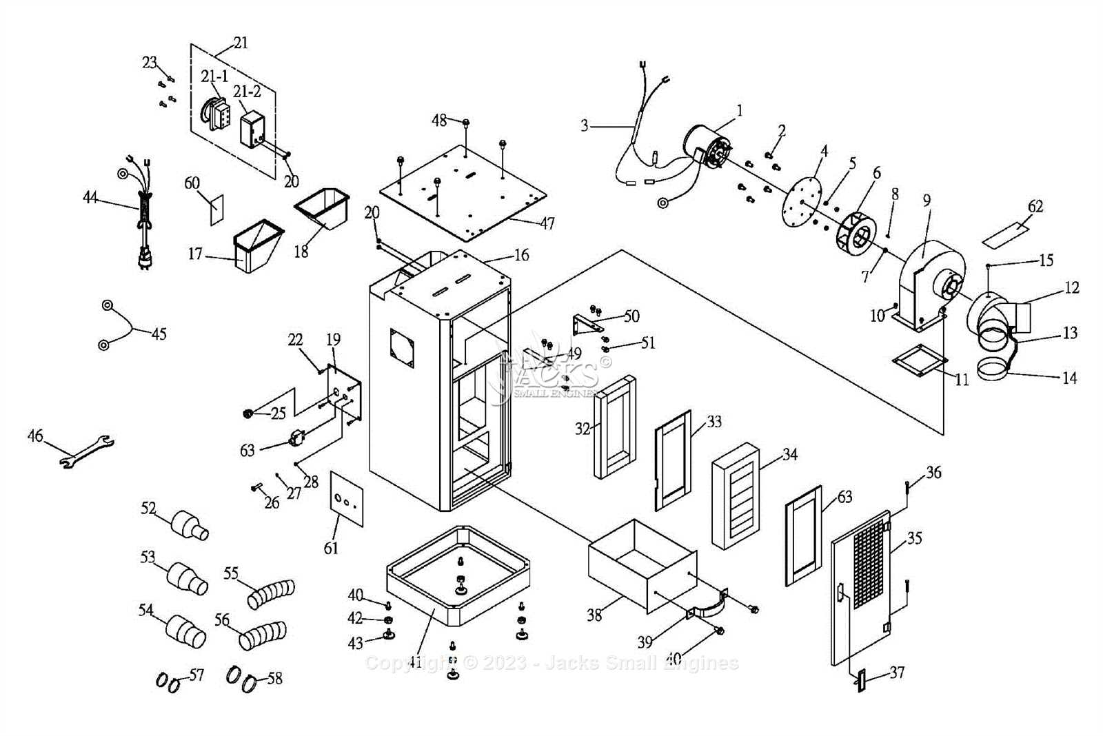
Internal parts like motors, control boards, and sensors are at the heart of many home appliances. These components are responsible for the core functionality of the device. Knowing where these elements are located and how they interact can aid in troubleshooting and identifying issues early on.
Connecting and Interacting Components
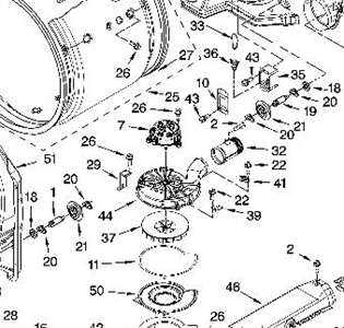
Beyond the core parts, there are various connections and small elements, such as wiring, connectors, and fasteners, that ensure smooth operation. These connections link different parts together, allowing them to work seamlessly. Understanding their role and layout within the appliance can prevent errors during repairs or when assembling disassembled units.
How to Read the Appliance Layout
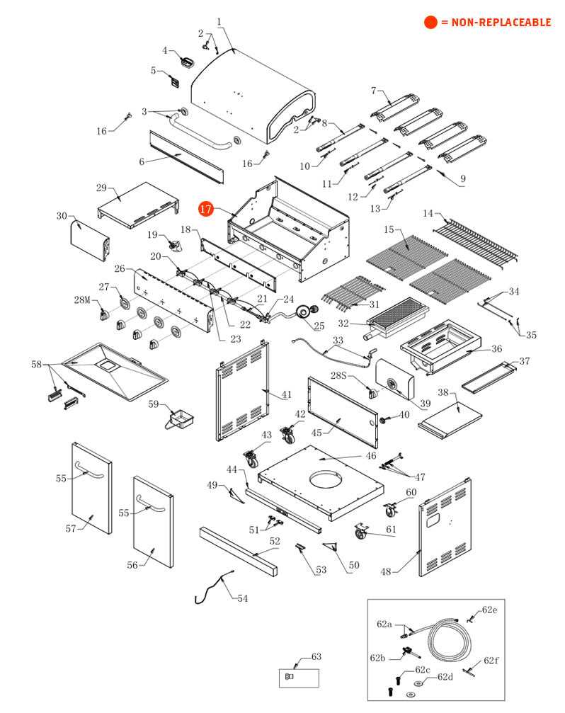
Understanding the layout of a household device is crucial for efficient repairs and troubleshooting. A well-structured visual guide provides a comprehensive view of the device’s internal organization, making it easier to identify each component’s role. Familiarity with these diagrams will help you quickly locate problem areas and prevent unnecessary mistakes during maintenance.
To interpret such illustrations effectively, it’s important to pay attention to key details that indicate the relationships between various parts. This involves recognizing symbols, labels, and connection points that indicate how the components interact.
- Symbols – Diagrams often use simple icons or shapes to represent different parts. Familiarize yourself with these symbols to identify elements like switches, motors, and connectors.
- Labels – Each part is typically labeled with a unique identifier or code. Make sure to match these labels with the parts in your unit to ensure accuracy during repairs.
- Connection Points – Look for lines or arrows indicating how parts are connected. This can help you understand the flow of energy or signals throughout the appliance.
By mastering the interpretation of these details, you’ll be able to make informed decisions during the repair process and handle any issues with confidence.
Common Issues and Solutions for Appliance Components
Every household device experiences wear and tear over time, leading to malfunctions that can disrupt its normal function. Identifying common issues and knowing how to resolve them can save both time and money. Understanding the typical problems and their solutions is essential for keeping these machines running smoothly for longer periods.
Frequent Mechanical Failures
Mechanical failures are often caused by worn-out components or faulty connections. Common issues include malfunctioning motors, broken belts, or jammed moving parts. In such cases, it’s crucial to pinpoint the faulty part and either replace or repair it to restore functionality.
- Check for any visible signs of wear or damage on moving parts.
- Ensure that motors are properly connected and free of obstructions.
- Replace damaged belts or misaligned gears to prevent further damage.
Electrical and Control Board Problems
Electrical issues such as power surges or faulty control boards can cause a device to stop working altogether. When these problems occur, the first step is to verify whether the power supply is functional. If the unit still doesn’t respond, a closer inspection of the control board or wiring may be needed to identify broken connections or burnt-out circuits.
- Test the power supply to ensure there is no disruption in the flow of electricity.
- Inspect the control board for visible damage or loose connections.
- Replace any damaged wiring or components on the control board for proper operation.