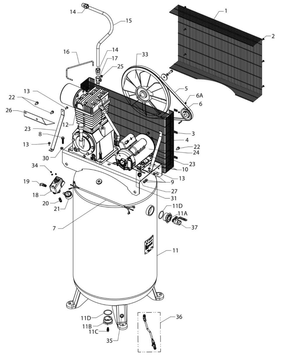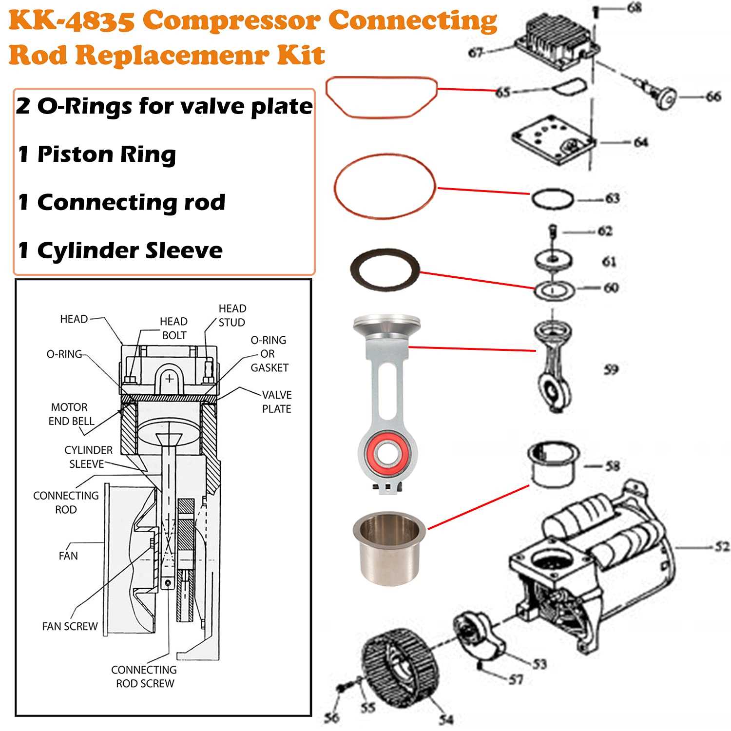
Knowing the internal structure of a pneumatic tool is essential for maintaining its performance and prolonging its lifespan. Recognizing the various components and their roles can help users troubleshoot issues more efficiently, making repairs less daunting and more cost-effective. Understanding how each element fits into the whole system empowers owners to identify potential problems before they escalate into major failures.
Having a visual representation of these essential components simplifies the repair process significantly. Whether you are assembling, disassembling, or performing routine maintenance, understanding the correct placement and function of each part can prevent common mistakes that could otherwise lead to inefficiency or damage. In this guide, we explore the critical pieces that make up the mechanism, offering a comprehensive look at their functions and interactions.
Understanding Key Components of Pneumatic Tools
Every mechanical system is made up of essential components that work together to ensure optimal functionality. When it comes to devices designed for pressurized systems, recognizing the key pieces that support the process is critical. These components range from the power source to the various valves, regulators, and other integral elements that control the movement of air or fluid. Each element plays a specific role, and understanding how they interact can make a significant difference in maintaining efficiency and preventing costly repairs.
Power Unit and Motor
The power unit is the core of any pneumatic system, providing the necessary force to drive the entire mechanism. Typically powered by electricity, this unit generates the energy needed to operate the system and ensure that the pressurized fluid is consistently circulated. The motor is closely tied to the power unit, and its health directly impacts the overall performance of the system.
Regulators and Valves

Regulators control the flow of air or fluid, ensuring the system operates within the specified parameters. These components are vital for maintaining consistent pressure levels and preventing overloads that could cause malfunctions. Similarly, valves direct the flow, controlling where and when the pressurized air is released or stored, making them indispensable in ensuring smooth operation.
How to Read a Parts Diagram Efficiently
Interpreting a visual representation of components is crucial for effective maintenance and repair. When you are faced with a schematic, understanding the layout and how each component is labeled can save time and reduce errors. A well-structured diagram provides a clear picture of where each piece fits into the overall system, making it easier to troubleshoot and replace faulty elements. By following a systematic approach, anyone can become proficient at reading these visuals and applying that knowledge to their repairs.
Familiarize Yourself with the Symbols
Before diving into the diagram, take a moment to familiarize yourself with the common symbols used to represent various components. Each element, such as valves, seals, and connectors, is often represented by a unique symbol. Understanding these symbols can help you quickly identify parts without having to read through extensive text descriptions. Additionally, many schematics include a key or legend to clarify what each symbol represents.
Follow the Flow of the System
As you examine the diagram, it’s essential to follow the flow of the system. This involves understanding how the components work together in a sequence to achieve the desired result. Pay attention to directional arrows and flow lines that indicate the movement of fluid or energy. By tracking the flow, you can gain a better understanding of how each part functions within the larger system.
Common Issues and Fixes for Pneumatic Tool Components
In any mechanical system, certain issues tend to recur due to the wear and tear of key elements. Understanding these common problems and knowing how to fix them can save both time and money. Whether it’s due to improper maintenance, wear, or manufacturing defects, recognizing the signs of malfunction early on is essential for effective troubleshooting. This section explores some of the most frequent issues that arise with pressurized systems and how to address them efficiently.
One common issue is the loss of pressure, often caused by leaks in hoses or seals. When a system isn’t holding pressure as it should, it significantly impacts its performance. Inspecting seals and connections for any visible signs of wear, cracks, or dirt buildup can help pinpoint the source of the problem. Replacing faulty seals or tightening loose connections usually resolves this issue quickly.
Another frequent issue is motor failure. This can be the result of overheating, electrical problems, or a malfunctioning power unit. Ensuring that the motor is kept clean and properly lubricated, as well as checking the electrical components for any signs of damage or wear, can prevent costly repairs. If the motor is overheating, it may be due to insufficient airflow, so cleaning the vents and ensuring proper ventilation is key to avoiding this issue.