When maintaining or repairing a mechanical system, having a clear visual representation of its individual parts can be invaluable. A well-structured chart or diagram allows users to easily identify each component and its function within the larger assembly. This understanding can significantly simplify the repair process and ensure that everything is reassembled correctly.
Whether you’re a DIY enthusiast or a professional technician, knowing how each piece fits together is essential. The visual reference serves as a guide, helping you to locate parts quickly and efficiently. By referencing the breakdown of individual elements, users can save time and avoid costly mistakes.
In this section, we?ll explore how to interpret these helpful guides, giving you the tools to approach your repairs with confidence. Understanding these visuals will not only enhance your maintenance skills but also increase the longevity of your equipment.
Understanding the Honda HR214 Parts Layout
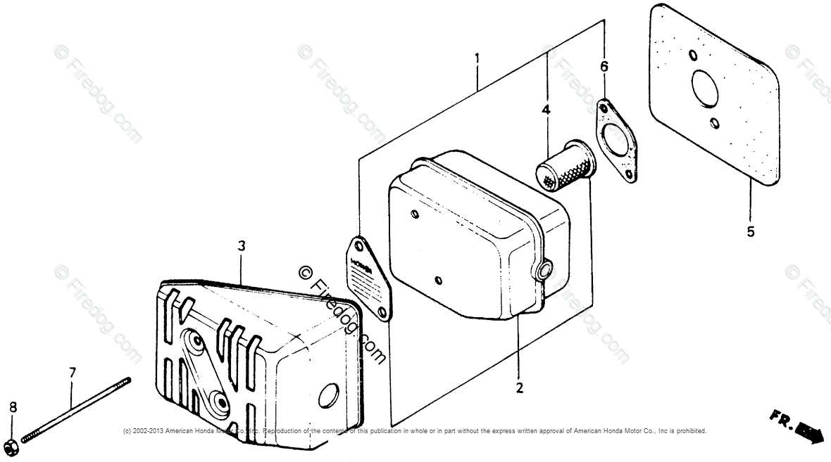
Having a clear overview of the internal structure of any mechanical device is crucial for effective maintenance and repair. A well-detailed layout showing the arrangement of each element within the system helps users comprehend how everything works together. By visualizing these components, users can more easily identify specific parts that require attention.
Key Sections of the System

The system is typically divided into several main sections, each contributing to the overall functionality. Understanding the role of each area helps streamline the troubleshooting process and guides users to focus on the correct components when performing repairs. These sections may include:
- Power System: The core mechanism responsible for energy transmission.
- Movement Mechanism: Elements that control motion and adjustments.
- Control System: Parts that regulate speed, direction, and other operations.
How to Read and Interpret the Layout

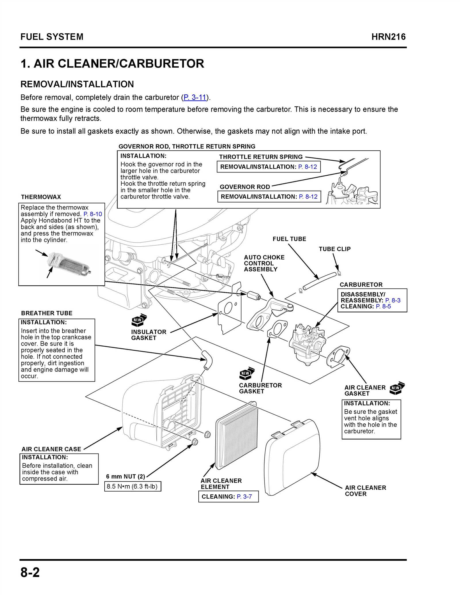
When referring to a layout, it?s important to know how to interpret the visual representation of each component. A detailed illustration will label each part, often with numbers or letters, allowing for easy identification. To use the layout effectively, follow these steps:
- Identify the section relevant to your repair.
- Match the labeled components with the physical parts on the system.
- Check for any wear or damage indicated in the illustration.
- Consult the system manual for part replacement instructions if needed.
With practice, users can become proficient at using these layouts to identify problem areas and ensure that each component is functioning as intended. This knowledge is essential for both preventive maintenance and efficient repairs.
Essential Components of the HR214 Model
Every mechanical system consists of key components that contribute to its overall performance. These critical elements work in harmony to ensure smooth operation and longevity. Understanding the function and location of each part allows for easier identification of issues and more effective maintenance.
The core components of this system include the engine, transmission, and control mechanisms, each responsible for different aspects of operation. While the engine powers the entire system, the transmission ensures proper movement and speed regulation. The control mechanisms are essential for directing the machine?s movements and adjusting settings based on user needs.
Additional important elements such as the wheels, frame, and various safety features further enhance the device?s performance, ensuring that it operates safely and efficiently. Being familiar with the layout of these components is vital for anyone performing repairs or maintenance tasks, as it helps prioritize which areas need attention.
How to Use the HR214 Parts Diagram

When dealing with any mechanical system, having a visual reference for its components can be invaluable. It provides clarity on how each element interacts with the others and guides users in identifying parts that may need repair or replacement. By understanding how to read and use these references, you can save time and avoid costly mistakes during the maintenance process.
Step-by-Step Approach
To make the most of the visual guide, begin by focusing on the major sections of the system. These are often labeled or highlighted to help you quickly identify the core components. Once you locate a particular area of interest, such as the engine or movement mechanism, pay attention to its individual parts. The reference will typically offer detailed labels, numbers, or letters to match each part to a corresponding real-world component.
Common Tips for Effective Use
Here are a few tips for using the visual guide efficiently:
- Identify Key Components: Start by locating the most important sections, such as the engine or control mechanisms.
- Cross-Reference with the Manual: Often, the guide will have a corresponding manual that provides additional details on each part.
- Use the Labels: Numbers or letters on the guide help to quickly match parts with the real-world model.
By following these steps, you can easily navigate through the parts and quickly identify areas in need of attention, ultimately improving the efficiency of your maintenance efforts.