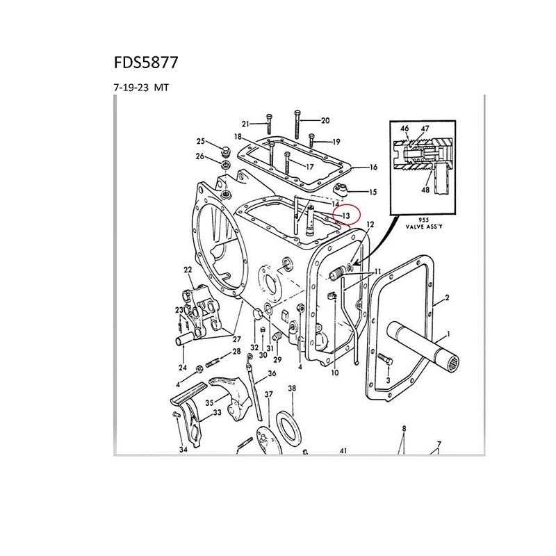
Farm machinery relies on a complex system of interconnected elements to perform various tasks efficiently. The inner workings of these devices are essential to ensure smooth operations, especially in demanding environments. Having a clear understanding of these components can significantly improve both maintenance and troubleshooting processes.
The schematic representation of these systems helps in identifying each part’s function and how they interact. By studying these layouts, operators can gain insights into repairs and replacements, ensuring their equipment remains in optimal condition. Knowing the function of each component is crucial for timely interventions and avoiding major breakdowns.
In this article, we will explore how to interpret these visual guides, providing you with the knowledge to enhance your understanding and take better care of your machinery. Understanding how these systems are designed and maintained can make a real difference in extending the lifespan and efficiency of your equipment.
Understanding Hydraulic System in Ford Tractors
The core functionality of modern farm machinery is often based on a fluid-based power system that controls a wide range of movements and functions. This system, integral to the operation of many heavy-duty machines, uses pressure from fluid to move parts that require high levels of force. Understanding how this system works is crucial for both operation and troubleshooting, ensuring the machinery performs optimally throughout its life cycle.
Key Functions of the Fluid-Based Power System
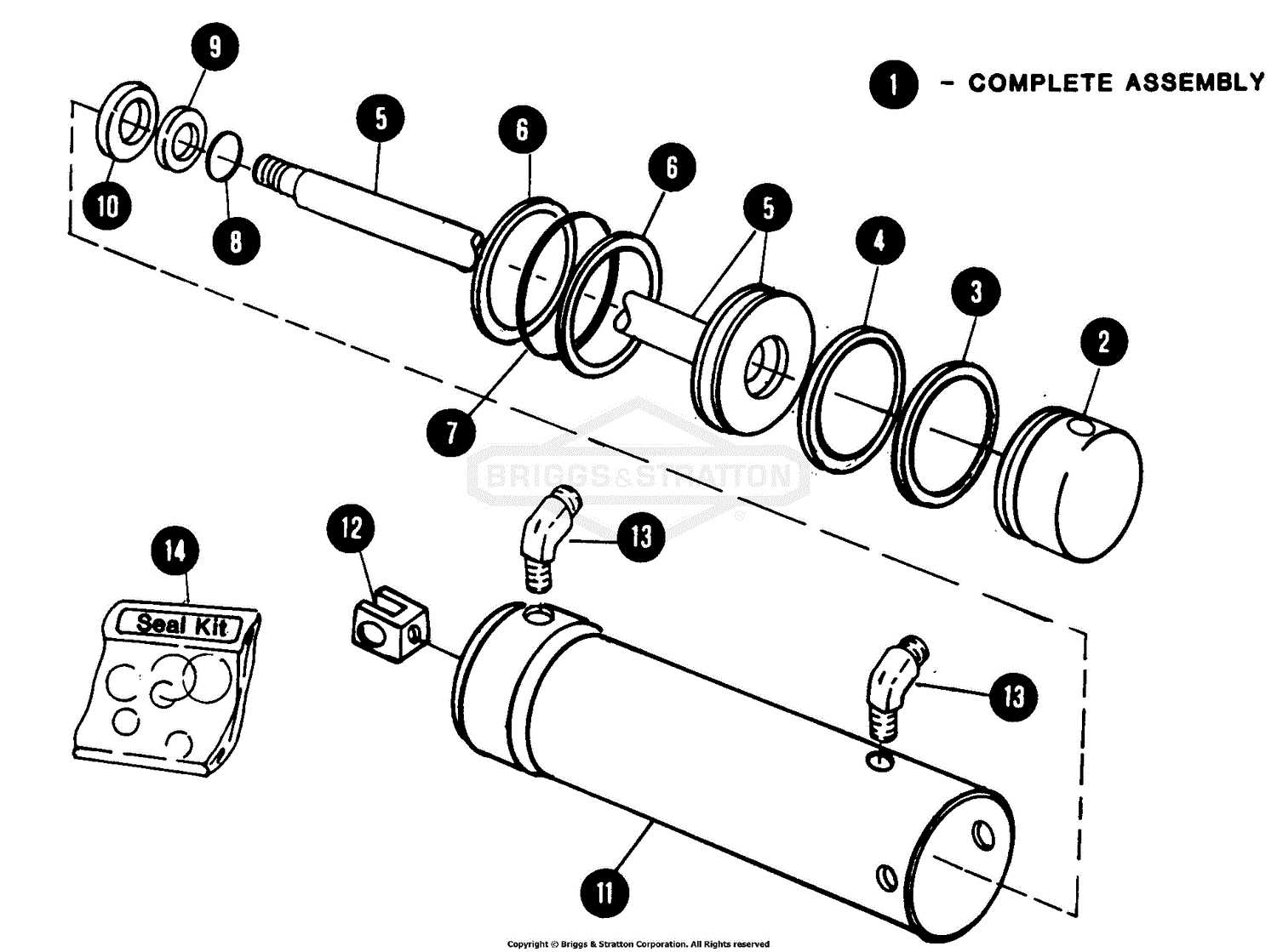
In these machines, fluid acts as the main medium to transfer force and movement. It powers components such as lifting mechanisms, steering, and other essential operations that require consistent strength. The flow and pressure of the fluid are controlled by various valves and pumps, which regulate the amount of energy delivered to each system based on need. Understanding these elements can help identify issues related to leaks, pressure loss, or malfunctioning components.
Maintenance and Troubleshooting Tips
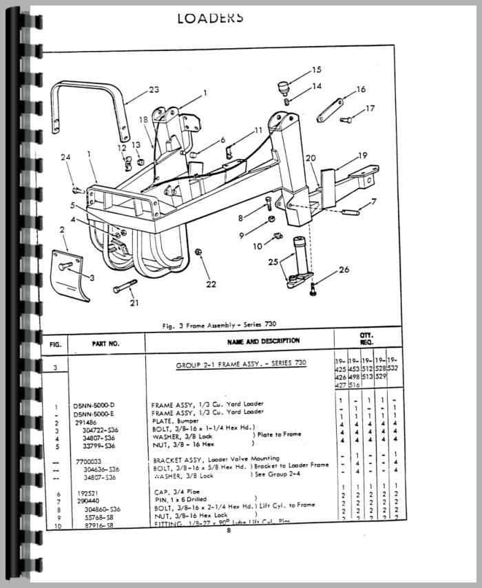
Maintaining the integrity of the fluid system involves regular inspections and the replacement of worn seals, hoses, and other components. Proper fluid levels and types must be maintained to ensure smooth operation, and any loss of pressure can significantly affect the machinery’s performance. Familiarizing yourself with the system’s layout and recognizing signs of wear can prevent costly repairs and improve the overall lifespan of the equipment.
Key Components of Hydraulic Ford Tractors
Every machine built for heavy-duty agricultural tasks relies on a set of interconnected systems, each designed to perform a specific role. These elements work in unison to provide force, control, and stability, which are essential for effective operation. Understanding the main components of the fluid-driven system is critical for both maintenance and repair efforts, ensuring that every part is functioning optimally.
Main Components
- Pumps: These devices generate the necessary pressure to circulate the fluid through the system, providing power for movement and lifting.
- Valves: Valves control the flow of fluid, directing it to the appropriate areas depending on the operational requirements.
- Reservoir: The fluid reservoir holds the fluid, allowing it to be drawn into the system and replenished during operation.
- Filters: Filters remove contaminants from the fluid, ensuring the system remains free of debris that could cause damage or reduce efficiency.
Additional Components
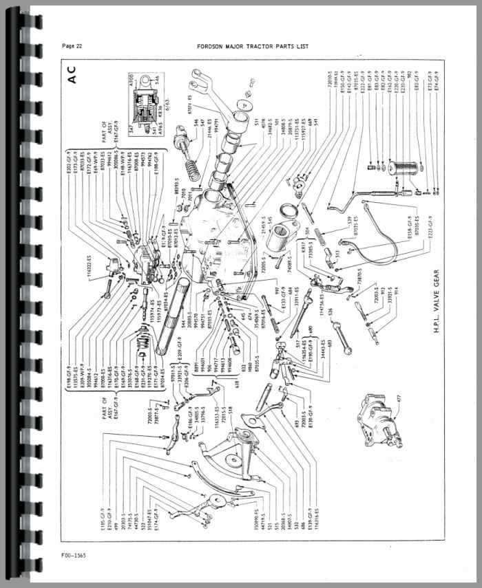
- Hydraulic Cylinders: These components convert fluid pressure into mechanical force, allowing for movement and control of equipment parts.
- Seals and Hoses: Proper seals and hoses prevent leaks and ensure that the fluid remains contained within the system, maintaining its pressure.
- Control Levers: These allow the operator to control the flow and direction of fluid, managing various actions such as lifting, lowering, or steering.
How to Read a Ford Tractor Parts Diagram
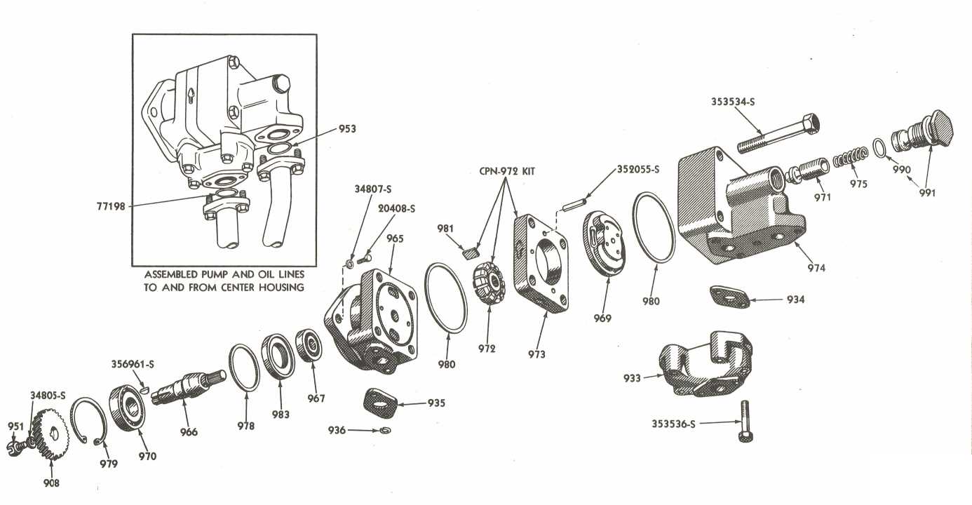
Understanding how to interpret machine schematics is an essential skill for anyone involved in maintenance or repair work. These visual guides break down complex systems into understandable segments, showing how various components are connected and function together. By learning to read these diagrams, operators and mechanics can quickly identify potential issues and understand how to troubleshoot effectively.
Each schematic is designed to represent the flow and interaction of various elements in a system. These visual aids typically use standardized symbols and labels to indicate specific parts, making it easier to trace the path of fluid, air, or power. Pay close attention to the legend or key provided with the diagram, as it will help clarify what each symbol represents and how the system is laid out.
When reading these guides, it’s important to focus on the main lines and connections. Identify the flow of energy or material, which is usually depicted by arrows or lines. These will guide you to understand how force is transferred throughout the system. Additionally, note any highlighted areas that indicate potential trouble spots or components that may require maintenance.