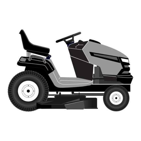
When maintaining your lawn equipment, it’s essential to have a clear understanding of its internal structure. A thorough breakdown of each element allows you to recognize the function of every piece and helps identify potential problems before they affect performance.
Knowing how to interpret a detailed schematic can significantly ease the repair process. By learning the layout and connections between different parts, you’ll be better equipped to perform maintenance tasks and troubleshoot any issues that arise.
Whether you are replacing worn-out components or simply checking for damage, a well-organized guide can save time and ensure your equipment remains in optimal condition. Understanding the role of each piece is crucial for anyone looking to extend the lifespan of their machinery.
Understanding Lawn Mower Components
Every lawn mower consists of multiple interconnected elements that contribute to its overall performance. Recognizing the role of each component is vital for efficient maintenance and troubleshooting. By familiarizing yourself with these individual parts, you can ensure smooth operation and extend the life of the machine.
Main Mechanical Components
The core of any mower includes the engine, transmission, and cutting mechanisms. The engine provides the necessary power, while the transmission controls the movement and speed. The cutting deck, blades, and associated mechanisms are crucial for efficient grass cutting. Understanding how these systems work together can help in diagnosing problems quickly.
Electrical and Control Systems
In addition to the mechanical parts, modern mowers also feature electrical systems that control various functions. These include the battery, wiring, and ignition components. The control panel, switches, and sensors allow the user to operate the mower safely and effectively. Being aware of these electrical elements ensures that you can address issues related to starting, power delivery, and safety features.
How to Read the Schematic
Interpreting a detailed schematic can be a crucial skill for understanding the layout and function of various components within your equipment. These visual representations serve as a guide, offering a clear view of the connections, positioning, and relationships between different elements. Knowing how to read them properly can help with maintenance, repairs, and part replacements.
Key Symbols and Notations
One of the first things to understand is the common symbols and notations used in these illustrations. These elements are designed to represent various mechanical and electrical components. Each symbol is standardized, which makes it easier to identify the part in question, even if you are unfamiliar with it. Here are some of the typical symbols you may encounter:
- Circles: Often represent moving components such as wheels or blades.
- Squares: Typically denote fixed or stationary parts like the frame or casing.
- Lines: Indicate connections between components or paths for energy and fluids.
- Shaded areas: Can indicate parts that require specific maintenance or are subject to wear.
Step-by-Step Approach to Reading
To interpret the schematic effectively, follow these steps:
- Identify the overall layout: Start by familiarizing yourself with the general structure and arrangement of components. This will provide context for specific parts.
- Locate the key parts: Once you understand the layout, identify the components that are of particular interest to your maintenance task.
- Understand the connections: Focus on the lines that represent links between parts. These often show how the parts interact, such as movement or power transmission.
- Look for part numbers: Many schematics include reference numbers that match to a list or catalog, helping you find exact replacements.
Common Issues and Replacement Parts
Even with regular maintenance, equipment may encounter certain common issues that require attention. These problems can range from mechanical failures to wear and tear of specific components. Identifying these issues early and knowing which parts need replacement can help keep the machinery running smoothly and prevent more costly repairs down the line.
One of the most frequent issues is with the cutting mechanism. Over time, the blades may become dull or damaged, affecting the quality of the cut. Replacing the blades with new ones ensures that the equipment operates efficiently and performs as expected.
Another common problem is related to the drive system. Worn-out belts or faulty pulleys can lead to a loss of power transmission, causing the equipment to slow down or stop working altogether. Replacing these components with high-quality replacements restores full functionality.
Battery-related issues are also prevalent, particularly in electrically operated models. A failing battery may prevent the engine from starting or cause the equipment to lose power unexpectedly. Replacing the battery ensures reliable performance and smooth operation.