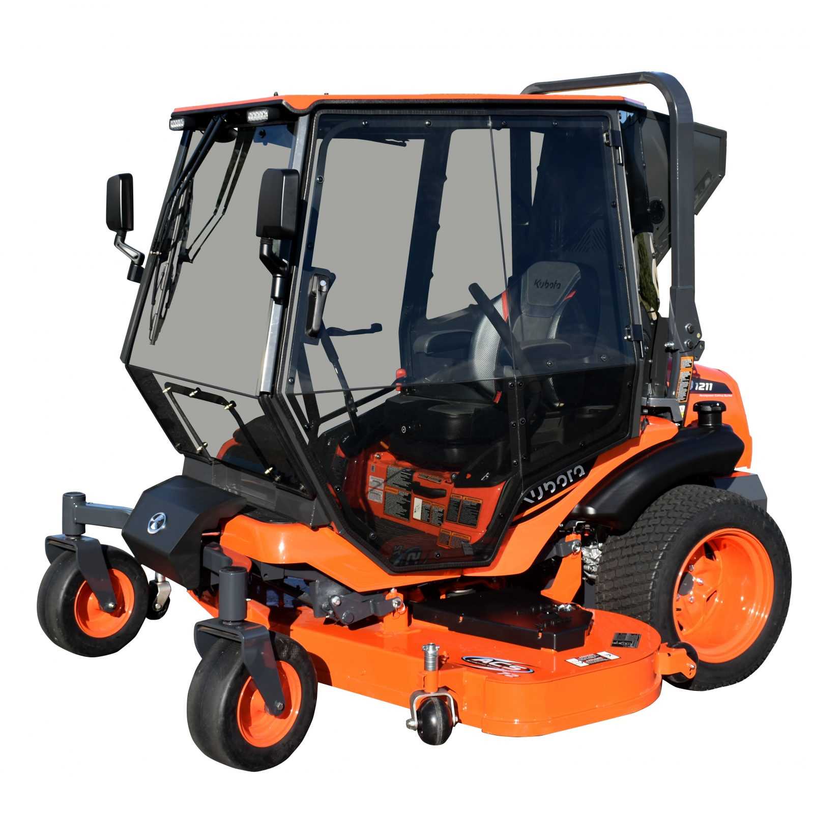
Maintaining machinery requires a clear understanding of its individual components. Identifying the various elements that make up your machine ensures proper care, efficient repairs, and prolonged use. This knowledge also aids in making accurate decisions when replacements or adjustments are necessary. Knowing how everything fits together is crucial for anyone involved in the upkeep of complex mechanical systems.
Through a detailed guide, you can explore the different sections and their functions, making it easier to pinpoint areas that need attention. Whether you’re replacing worn-out parts or conducting routine inspections, this resource provides essential visual references. A comprehensive look at the internal structure enhances your ability to manage tasks confidently and effectively, ultimately improving the longevity and performance of your equipment.
Understanding the Kubota ZD1211 Components
When working with machinery, knowing the function and structure of each element is essential for smooth operation and effective troubleshooting. Every machine consists of multiple interconnected systems that work together to achieve optimal performance. Understanding these components allows users to make informed decisions about maintenance and repair, reducing downtime and improving reliability.
Main Mechanical Systems
The main systems within the machine are designed to handle the primary functions, such as power generation, motion, and stability. These include the engine, transmission, and drivetrain, which all play a critical role in ensuring that the machine operates efficiently. Proper care and understanding of these systems help prevent failures and improve overall durability.
Supporting Components
In addition to the main systems, there are several supporting elements that enhance performance and safety. These components manage functions like cooling, lubrication, and control. Identifying and maintaining these supporting parts ensures the longevity of the core systems and prevents breakdowns due to wear and tear.
Key Parts of the Kubota ZD1211 Engine
The heart of any engine lies in its core components, each designed to perform a specific function that contributes to the overall operation. Understanding the key elements is vital for anyone working with machinery, as it helps in diagnosing issues and performing routine maintenance tasks. These essential parts work together to ensure the engine runs smoothly, efficiently, and reliably.
Engine Block and Pistons
The engine block is the central unit where all mechanical action takes place. Inside the block, pistons move up and down, creating the power needed for the machine to operate. These components must be kept in excellent condition, as they are subject to high levels of stress and heat. Regular inspection and maintenance are necessary to avoid performance issues.
Fuel System and Air Intake
The fuel system and air intake are responsible for supplying the engine with the necessary elements to ignite and burn fuel. These systems must function together to provide the correct fuel-air mixture for optimal combustion. Any blockage or malfunction in these systems can lead to poor engine performance or even failure.
How to Use the Kubota ZD1211 Diagram
Having access to a detailed visual reference of your machinery is crucial for efficient repairs and maintenance. Understanding how to read and utilize such resources allows you to identify components quickly and accurately, ensuring that issues are resolved effectively. This guide will walk you through the key steps to make the most of the schematic for your machine.
Identifying Key Components
First, familiarize yourself with the layout of the schematic. It is divided into sections based on the various systems within the machine, such as the engine, transmission, and electrical components. Each part is labeled clearly, allowing you to identify specific elements within these systems. Pay close attention to any notes or special instructions that may appear alongside the diagrams.
Using the Reference for Maintenance and Repairs
Once you understand the layout, the diagram becomes an essential tool for troubleshooting and repairs. When issues arise, refer to the relevant section to pinpoint the malfunctioning component. With this visual aid, you can quickly determine what needs to be replaced or adjusted, saving time and reducing the risk of errors during the repair process.