When it comes to maintaining your outdoor machinery, knowing the internal structure is essential for proper upkeep and repair. Each component plays a crucial role in the overall function of the system, ensuring smooth operation and longevity. A clear understanding of how these elements work together can prevent common issues and extend the life of the equipment.
Identifying individual parts and recognizing their positions within the system is the first step in troubleshooting or performing maintenance. This knowledge allows you to address specific problems quickly and efficiently. Whether you’re dealing with wear and tear or simply performing routine checks, knowing the layout can make the process much simpler.
Mastering the assembly is also helpful when it comes to upgrades or replacements. Recognizing compatible parts and knowing where to find them can save you time and effort, especially when sourcing replacements. Understanding how the system operates as a whole gives you confidence in performing tasks that might otherwise seem daunting.
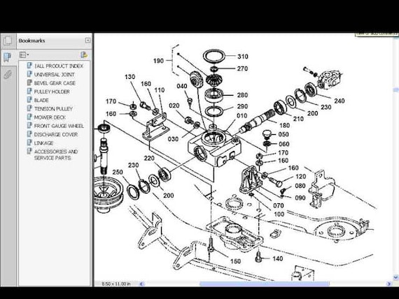
Understanding Kubota 60 Deck Components
Each piece of outdoor machinery has a unique configuration of elements that work together to ensure smooth functionality. Familiarity with these components is crucial for anyone seeking to maintain or repair the equipment effectively. By recognizing how the individual components interact, you can identify issues and perform accurate troubleshooting.
The structure of the system is built around several key components, each contributing to the overall performance. Some of the most important elements to focus on include:
- Transmission elements: These control the flow of power from the engine to various parts, ensuring optimal movement.
- Cutting mechanism: The rotating components responsible for trimming grass, requiring regular attention to stay sharp and efficient.
- Support structure: The frame that holds everything in place, offering stability during operation and ensuring parts are aligned correctly.
- Control system: The system of levers, buttons, and other controls that allow the user to manage the machine’s operations.
Each of these elements plays an important role in achieving the desired results, and understanding their function will allow you to perform accurate maintenance. It’s essential to recognize the relationship between them, as it can provide insights into how to address any malfunction or wear-related issues effectively.
Key Parts of the Mower Deck
Understanding the main components of outdoor equipment is essential for ensuring its efficient operation. Each part is designed to serve a specific function, contributing to the overall performance and durability. By focusing on the key elements, users can quickly diagnose issues and perform targeted maintenance to keep the equipment running smoothly.
Cutting Mechanism

The cutting system is at the heart of the machine’s functionality. It is responsible for creating an even and precise cut, which requires several key components to work in harmony. The rotating blades are powered by the engine and are designed to remain sharp for maximum effectiveness. Regular inspection and maintenance of these blades are critical to prevent uneven cuts or inefficient operation.
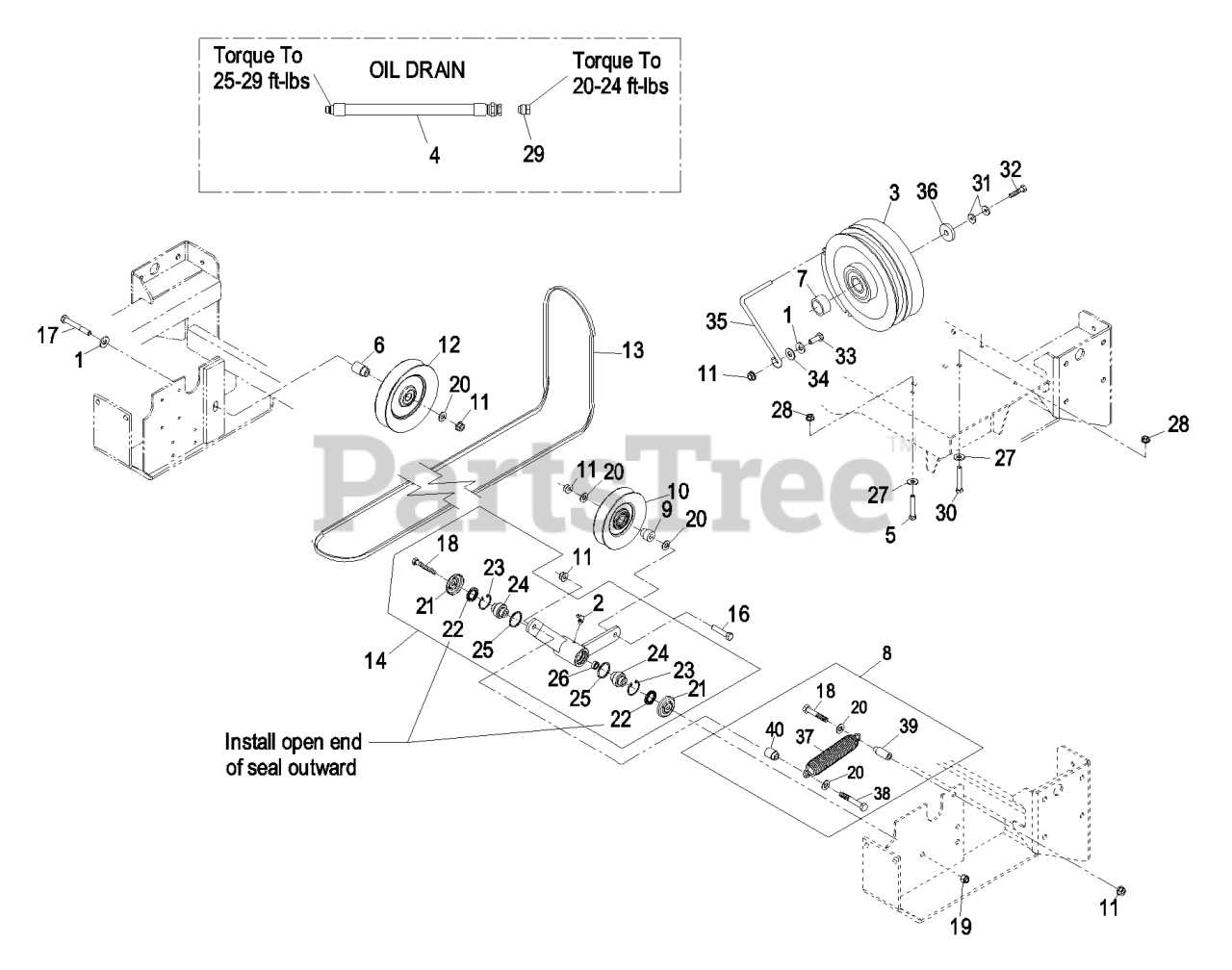
Transmission and Drive Components
The transmission system transfers power from the engine to various parts of the machine, enabling movement and action. Key elements such as the drive belts and pulleys help control the speed and direction of the equipment. Ensuring that these components are properly aligned and in good condition can prevent wear and costly repairs.
How to Interpret the Diagram Effectively
Interpreting a schematic can be an invaluable skill when it comes to understanding the layout and function of complex equipment. Whether you’re troubleshooting, assembling, or performing maintenance, a clear understanding of how to read these visual representations can save time and reduce errors. The key is to focus on the relationships between components and how they interact within the system.
Start by identifying the main sections and their respective functions. Most diagrams will break down the system into easily recognizable parts, each labeled clearly for easy reference. Pay attention to any color coding or symbols that can provide additional information on the operation of specific components.
Next, focus on the flow of energy or power through the system. This is often represented by arrows or lines, guiding you through the sequence of actions that occur as the equipment operates. Understanding this flow can give you insights into how and where a malfunction might occur.
Lastly, make sure to cross-reference the diagram with the physical machine whenever possible. This hands-on approach can help you visualize the layout and confirm that your interpretation of the schematic is accurate. By combining theory and practice, you can improve your troubleshooting and repair skills significantly.