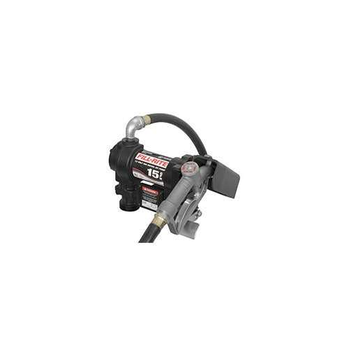
When working with mechanical systems, it’s crucial to comprehend the individual elements that contribute to their efficient operation. Each component plays a specific role in ensuring the system runs smoothly, and understanding how they interact can help in maintenance, troubleshooting, and optimization. This section aims to provide a clear understanding of these essential elements, focusing on their structure and relationship within the broader system.
Recognizing the importance of each component is the first step in mastering any mechanical device. With a detailed map of each part, users can quickly identify potential issues and take appropriate action. Whether you’re repairing or upgrading, knowing the function and placement of every part enhances your ability to work effectively.
By delving into the specifics of the structure, users can gain insights into how each part contributes to the overall function. This knowledge is vital not only for proper operation but also for troubleshooting, helping prevent damage and ensuring long-term reliability.
Understanding the 15 GPM Fluid Transfer System
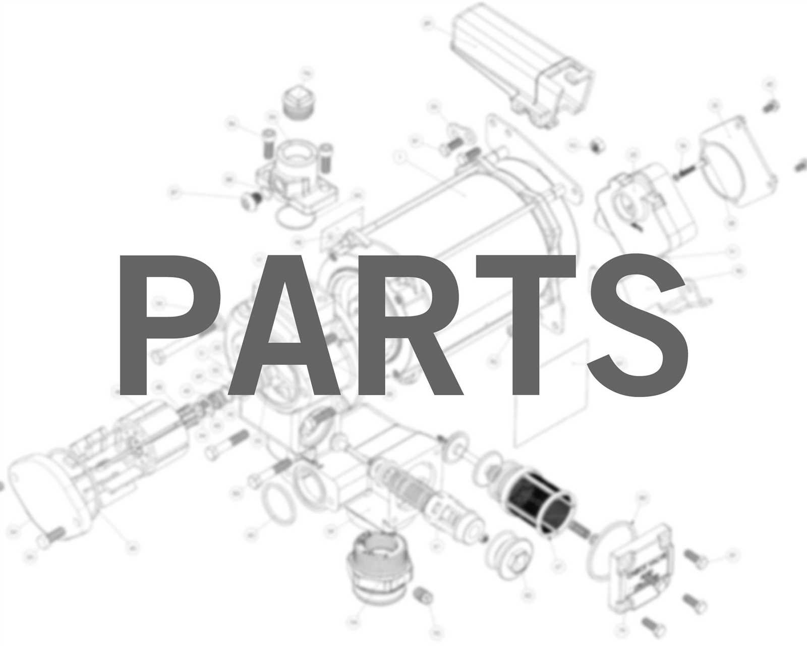
In any fluid transfer setup, knowing how each part of the mechanism works together is essential for smooth operation. This system, designed for high-flow capacity, features a combination of key elements that allow for efficient movement of liquids. Understanding how these elements are structured and how they interact is crucial for both optimal use and troubleshooting.
The core function of this system is to provide a reliable method for transferring liquids in a variety of environments. Every component, from the motor to the delivery mechanism, is engineered to support consistent operation. A deep understanding of its layout helps identify where issues may arise, allowing for faster repairs and maintenance.
Each part is designed with durability and functionality in mind, ensuring the system can handle the demands of high-volume liquid transport. By familiarizing yourself with the configuration and roles of these elements, users can make informed decisions when it comes to adjustments, upgrades, or repairs.
Key Components of the Transfer System
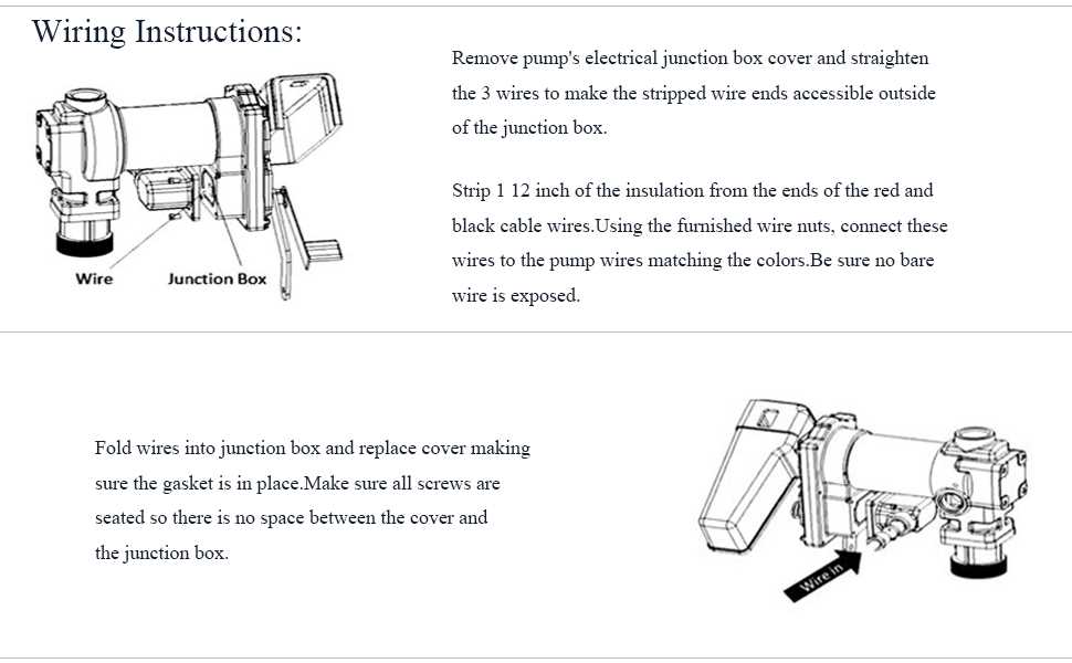
Every fluid transfer system is made up of several crucial elements that work together to ensure effective and reliable operation. Understanding the role of each component is essential for both performance and maintenance. Each part contributes to the overall efficiency and helps ensure the system runs smoothly under varying conditions.
The motor serves as the heart of the system, providing the necessary power to drive the flow of liquid. Coupled with the right intake and outlet mechanisms, the motor enables the movement of fluid from one place to another. The flow control and filtration units are also integral, as they regulate the speed and quality of the liquid being transferred, ensuring optimal performance and reducing the risk of damage to the system.
Another key element is the housing, which protects the internal components from external factors and maintains the structural integrity of the system. By understanding the layout and function of these components, users can troubleshoot more effectively and ensure long-term reliability.
How to Read the System Layout
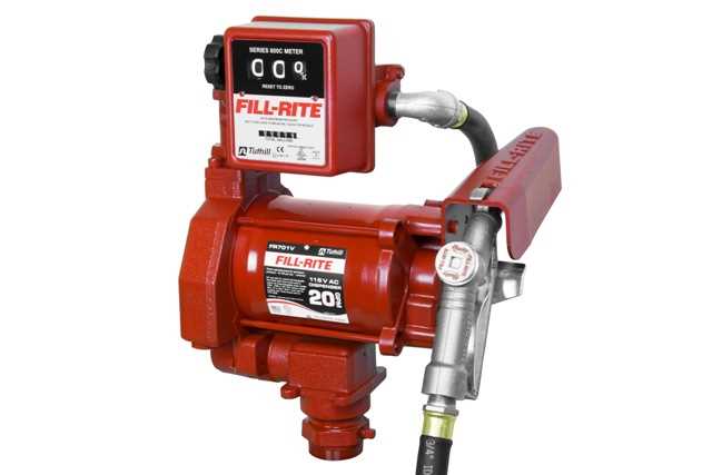
Interpreting a system layout is an essential skill for anyone working with mechanical or fluid transfer systems. It provides a visual representation of how the various components are arranged and how they function together. By reading and understanding this layout, users can gain insight into the structure and organization of the entire setup, making it easier to identify components and troubleshoot potential issues.
Identifying Key Elements
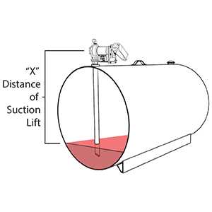
The first step in reading any layout is identifying the main elements. Each component is typically labeled with a reference number or code, which corresponds to a detailed description elsewhere in the manual or guide. These labels allow users to quickly locate the part in question and understand its specific function within the system.
Understanding Flow and Connectivity
Another crucial aspect of the layout is understanding how the components are connected and how fluids or energy flow through the system. Arrows or lines often indicate flow directions, making it clear how one part interacts with another. By carefully following these indicators, users can track the entire process from start to finish and identify any points where issues may arise.