When working with industrial equipment, it’s crucial to understand the intricate components that work together to ensure efficient operation. Visual aids can help illustrate the specific elements that play a role in the system’s functionality. By examining how each piece interacts with others, users can troubleshoot, maintain, and optimize the machinery with greater ease.
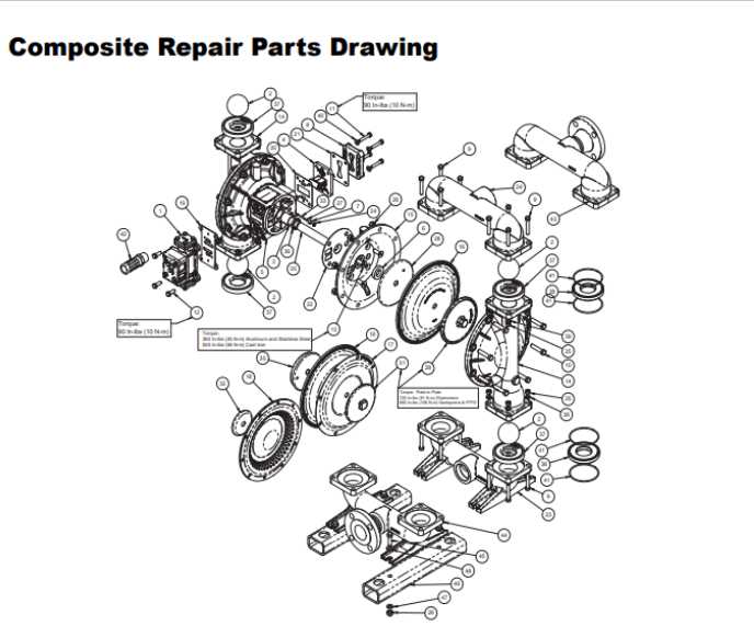
Detailed schematics provide valuable insight into the various components of the system. They are essential tools for anyone seeking to gain a deeper understanding of the mechanical processes involved. These visual resources allow operators to quickly identify and assess the condition of each element, ensuring better decision-making in maintenance or repair tasks.
Grasping the layout and design of these elements can significantly enhance your ability to address potential issues before they escalate. Whether for routine checks or more complex repairs, mastering the diagrams of the system is an indispensable skill for operators and technicians alike.
Understanding Sandpiper Pump Components

In industrial machinery, each element plays a crucial role in maintaining efficiency and ensuring optimal performance. A comprehensive understanding of how these components interact allows for smoother operations, easier troubleshooting, and more effective maintenance practices. With a focus on mechanical systems, it’s essential to familiarize oneself with the various components that contribute to the overall function.
Key Elements of the System
The system relies on a combination of internal and external components that work in harmony to achieve desired results. From valves to seals, each part is engineered for a specific function, whether it’s controlling fluid flow, maintaining pressure, or providing stability during operation. Recognizing these components and their roles can help users identify areas that may require attention during regular inspections or repairs.
Interconnection and Functionality

The true strength of the system lies in the interconnection of each element. Understanding how these parts interact allows technicians to diagnose issues more efficiently. It also highlights the importance of maintaining each individual component, as failure in one area can lead to a cascading effect that disrupts the entire system. By mastering the layout and function of each part, operators can ensure consistent performance and longevity of the equipment.
Identifying Key Parts in Sandpiper Pumps
Understanding the essential components of fluid-moving systems is crucial for ensuring their efficient operation. Each unit is made up of various elements that work together to facilitate fluid transfer. Recognizing the specific functions and placements of these components aids in troubleshooting, maintenance, and overall performance enhancement.
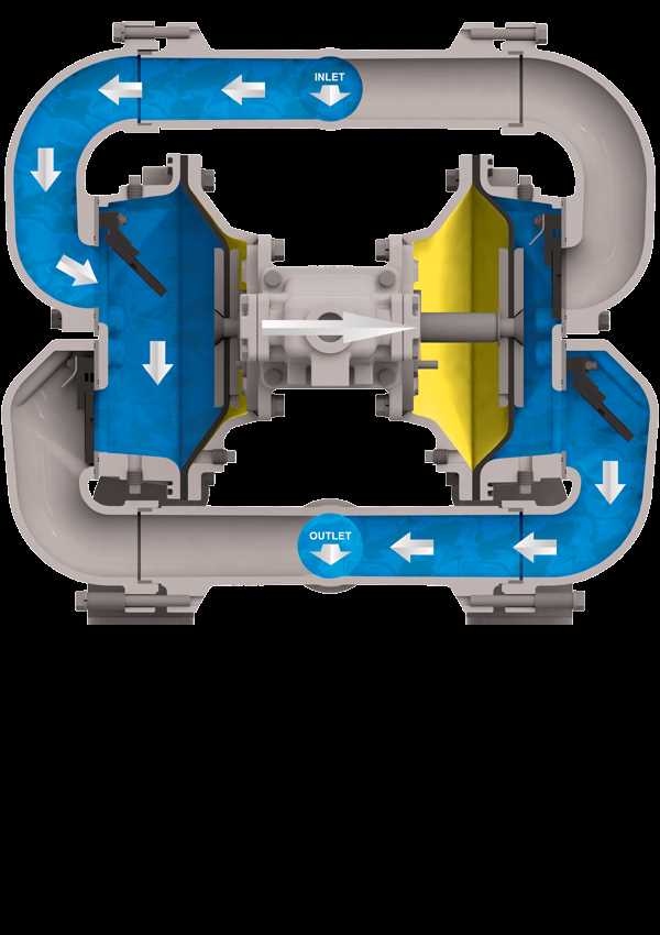
One of the main elements is the driving mechanism, which converts energy into motion, enabling the system to operate smoothly. Another vital part is the sealing component, responsible for preventing leaks and ensuring the integrity of the system. Additionally, the inlet and outlet channels serve to manage the flow direction, maintaining steady fluid movement throughout the system.
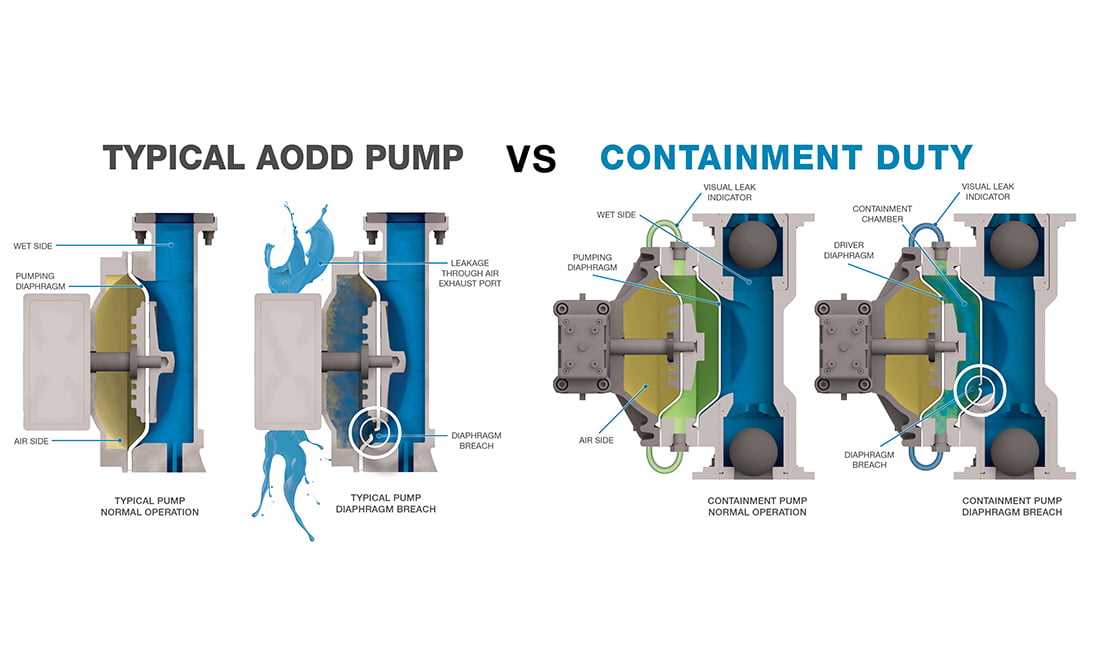
The diaphragm is another significant feature, playing a key role in creating pressure variations to move the fluid. Support structures also contribute to the overall stability and durability of the entire assembly. Finally, the control mechanisms, which allow for adjustments to flow rates and pressures, are essential for optimizing the system’s performance under various conditions.
How to Read Sandpiper Pump Diagrams
Interpreting technical illustrations is key to understanding the functionality of a fluid-moving system. These visual representations offer a detailed overview of various components and their connections, which is essential for both troubleshooting and maintenance. Familiarizing oneself with the common symbols and layout is the first step in reading these charts effectively.
Understanding the Layout

The first thing to look for is the overall structure of the schematic. It often includes labeled lines that indicate the flow of the fluid, showing how it moves through the system. Key parts are usually represented by specific symbols that are consistent across various models. Identifying these symbols helps in recognizing how each element interacts with others.
Interpreting Specific Symbols
Each diagram uses standardized icons to represent components such as valves, seals, and diaphragms. Arrows typically indicate the direction of movement or pressure changes. Understanding the meaning of these symbols is crucial for correctly interpreting the chart. Often, a legend or key will accompany the diagram, providing definitions for these icons and their functions within the system.