In the world of welding, the tools and accessories you use are crucial for achieving precise and efficient results. Every welder relies on specific equipment that consists of various interconnected elements, each serving an essential function in the welding process. Knowing how these components work together ensures smooth operation and helps you troubleshoot any issues that may arise during your tasks.
Proper knowledge of the different pieces of equipment can significantly enhance your understanding and ability to maintain your tools. Each part plays a key role in the overall performance, from feeding the wire to controlling the flow of electricity. The ability to identify and comprehend the function of these elements allows welders to work more effectively and safely.
In this guide, we will explore the essential components of welding equipment, helping you understand how each part contributes to the quality of your work. By learning to read and interpret the system’s structure, you can maximize your tool’s performance and ensure lasting durability.
Understanding the Tweco MIG Gun Parts
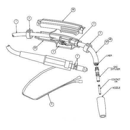
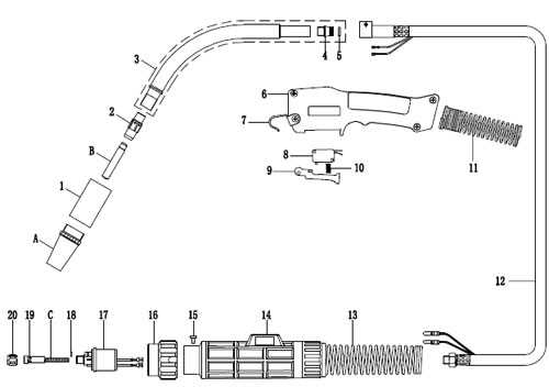
Welding tools are composed of various elements that work together to ensure the success of a welding project. Each component within the assembly serves a specific function that contributes to the overall performance of the equipment. Familiarizing yourself with the different parts helps maintain and repair your tools effectively while improving the quality of your welds.
Essential Components and Their Functions
The main components of welding equipment are designed to handle both the electrical and mechanical aspects of the welding process. For instance, the nozzle directs the flow of the wire, while the electrode holder ensures the electrical connection remains stable. Understanding how these parts interact is essential for seamless operation.
Maintenance and Troubleshooting Tips
Regular inspection and maintenance of each part are crucial for preventing wear and tear. Common issues, such as poor feed or overheating, can often be traced to specific components. Ensuring that all parts are clean and well-maintained extends the tool’s lifespan and improves welding results. Troubleshooting begins with knowing how each piece functions and how to spot problems before they impact your work.
Key Components of a MIG Gun

Every welding tool comprises a series of interconnected elements, each designed to perform a specific task to ensure smooth and efficient welding. These components work together in harmony to produce precise results while allowing the operator to maintain full control throughout the process. Understanding the role of each part is essential for optimal performance and longevity of your equipment.
Wire Feeding Mechanism

The wire feeding system is one of the most important elements, as it continuously supplies the welding wire to the work area. This mechanism ensures the wire moves smoothly, without interruption, allowing for consistent welds. Common components involved in this process include the drive rolls and liner, which guide and push the wire with precision.
Contact Tip and Nozzle
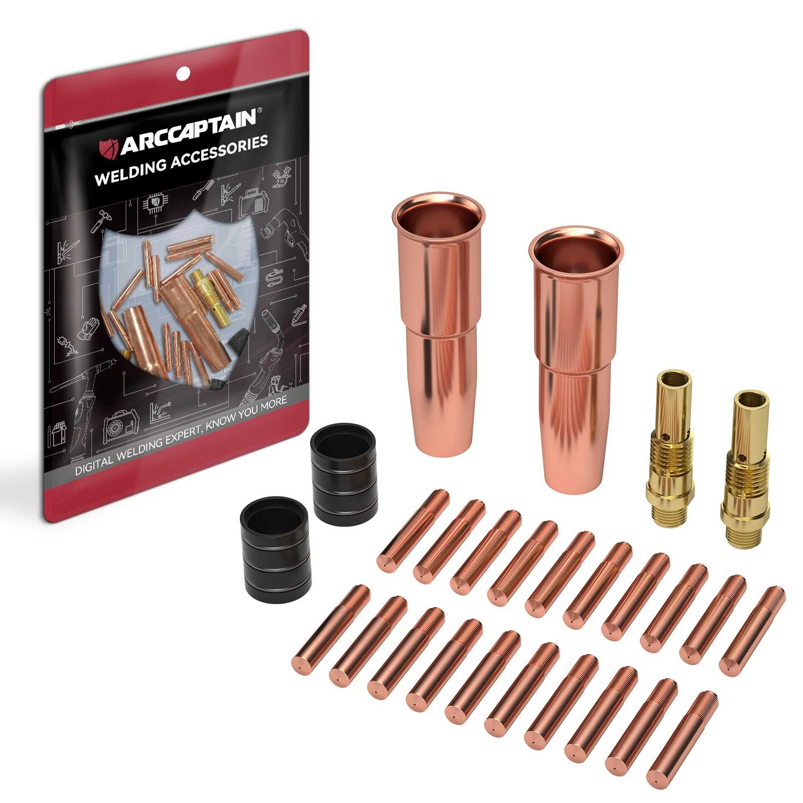
The contact tip plays a crucial role in the welding process by creating a stable electrical connection between the wire and the material. The nozzle protects the tip and directs the shielding gas to the welding area, preventing contamination and ensuring high-quality welds. Both parts require regular inspection and cleaning to maintain proper function.
How to Read a MIG Gun Diagram
Understanding technical illustrations is a vital skill for anyone working with welding equipment. These diagrams provide a clear, visual representation of how different components are arranged and interact with one another. Learning how to interpret these drawings allows for more efficient repairs, maintenance, and troubleshooting.
When reading a technical drawing of a welding tool, follow these key steps:
- Identify the Labels: Each component will be labeled with its name or part number. This helps in easily referencing and understanding the role of each element.
- Understand the Connections: Look for lines that show how components are connected. Solid lines often represent physical connections, while dotted lines may indicate electrical or gas flow pathways.
- Note the Scale: Ensure that the diagram includes a scale, which will help you understand the relative size of the components and how they fit together in reality.
By following these basic principles, you’ll be able to fully understand the structure and function of the equipment. This knowledge can help you maintain your tools more effectively and ensure a more precise welding process.