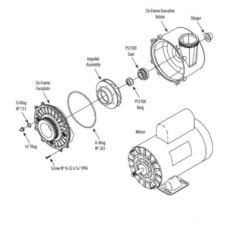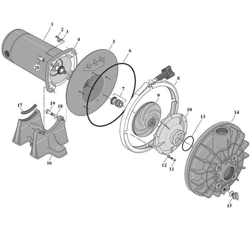
When dealing with any fluid circulation system, it is essential to understand the inner workings and the various elements that contribute to its functionality. Knowing how each component works together ensures efficient operation and easier troubleshooting in case of failures.
Identifying individual components plays a crucial role in maintenance. Each piece has a unique function, from the motor to the valves, and understanding their roles helps in diagnosing issues effectively.
Understanding system diagrams can simplify the process of repair and optimization. These visuals serve as a guide to recognizing the interaction between parts and provide valuable insights into the assembly, making it easier to maintain performance.
Understanding Pump System Components

The effectiveness of any fluid-moving system relies on the interaction between its key elements. Each individual component has a distinct function that contributes to the overall efficiency and reliability of the mechanism. Recognizing how these components work together can help identify issues more quickly and enhance performance.
Central to the operation are the motor and the control mechanisms, which drive the system’s flow. These components are responsible for regulating speed and direction, ensuring that the system operates as intended. Additionally, parts that manage fluid intake and output are essential for maintaining smooth operation.
Understanding these components allows for better decision-making during maintenance. Identifying worn-out or malfunctioning parts can prevent larger issues down the line, saving time and cost in the long run. Proper knowledge of each element’s role enables more effective troubleshooting and repairs.
Key Elements of a Fluid Circulation System
To ensure a fluid-moving system operates efficiently, it is essential to understand its core components. Each part has a specialized function that contributes to the smooth flow and overall effectiveness of the system. Understanding these elements is crucial for proper maintenance and troubleshooting.
The motor serves as the driving force, providing the necessary power to initiate movement. Coupled with the control mechanisms, it regulates speed and flow direction. Equally important are the intake and discharge valves, which manage the fluid entering and leaving the system, ensuring optimal performance.
The system’s housing or casing plays a protective role, enclosing the internal components and preventing damage. Additional accessories such as seals and gaskets maintain pressure integrity, while filters help remove debris that could compromise efficiency. Together, these components form the backbone of a reliable system.
How to Read a Fluid System Blueprint
Understanding a blueprint for a fluid system can seem complex, but with the right approach, it becomes a valuable tool for maintenance and troubleshooting. These visuals represent the relationships between various elements, showing how each part interacts within the whole system. By recognizing the key features, you can easily navigate through the design to identify potential issues or make necessary adjustments.
Identifying Key Components
Start by locating the main components, which are usually highlighted or represented with specific symbols. These might include the motor, valves, and piping that control the fluid flow. Recognizing these elements will help you understand how the system operates at a glance.
Understanding Flow and Connections
Next, focus on the lines and arrows, which indicate the flow path and direction. These markings will guide you in understanding how the fluid moves through the system and where it may be redirected or controlled. By following these connections, you can pinpoint the exact route and identify any blockages or inefficiencies.