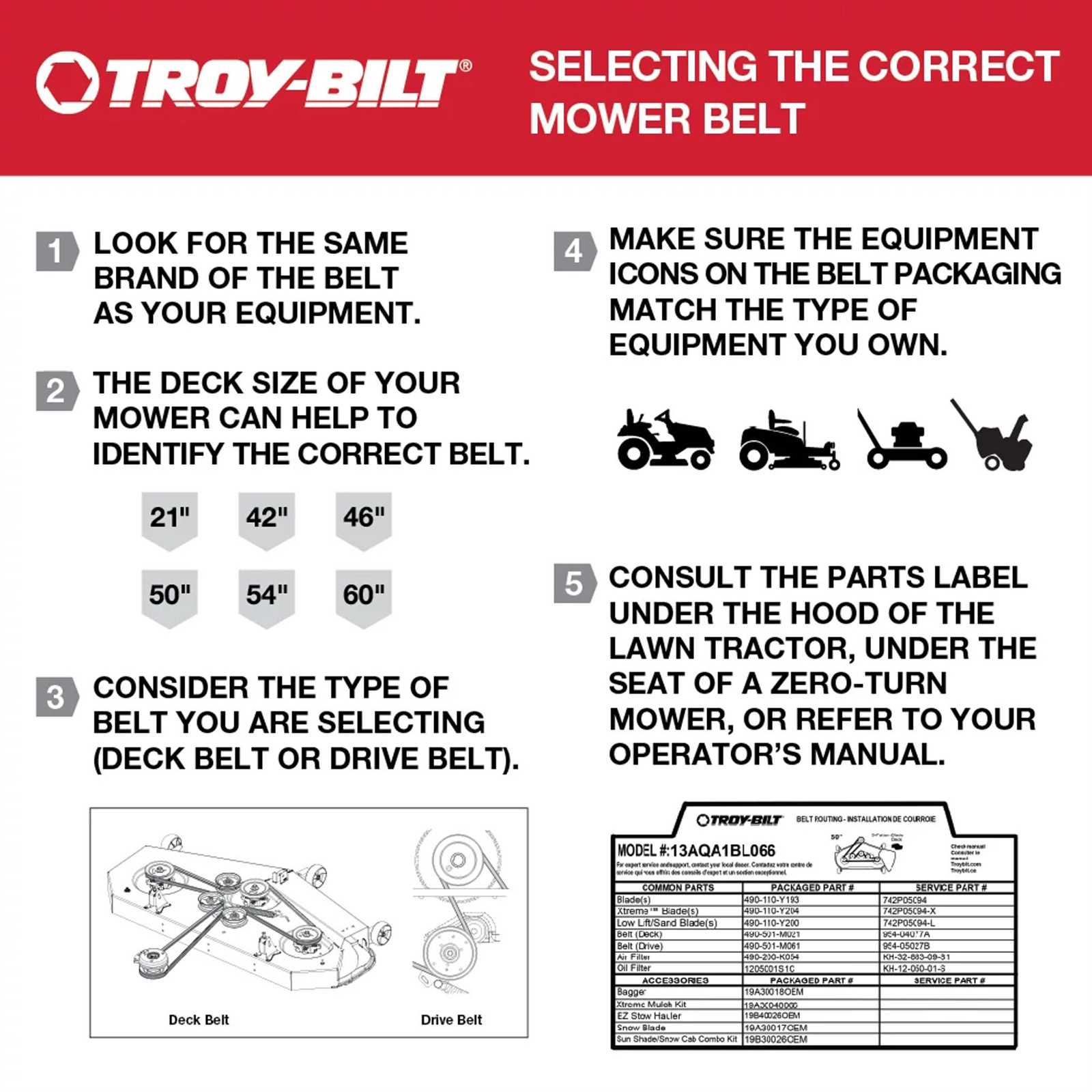
Maintaining and repairing machinery requires a clear understanding of how its components fit together and function. Having a visual reference to identify individual parts can save time and ensure accuracy when making replacements or performing maintenance. This guide will help you navigate through essential details that aid in identifying specific components, making repairs simpler and more efficient.
Understanding the layout of any complex system is crucial. Whether you’re fixing a lawnmower, tractor, or another piece of machinery, each part must be correctly matched to its counterpart. A detailed reference allows for a more organized approach to troubleshooting, minimizing errors and enhancing the overall repair process.
Knowing how to interpret these visual references is the first step toward successful maintenance. By familiarizing yourself with the placement and purpose of each element, you can proceed with confidence, reducing downtime and improving the lifespan of your equipment.
Understanding the 13ab77bs023 Parts Diagram
When dealing with mechanical equipment, having a clear visual representation of all the components is essential. Such an illustration provides an organized view of how each element is positioned and interacts within the larger system. With this reference, you can easily identify the specific parts you need to focus on during maintenance or repair tasks.
By studying these detailed visuals, you can break down complex systems into manageable sections. This structured approach allows you to identify individual pieces and understand their functions within the broader mechanism. Recognizing the correct placement and connection of each component ensures a smoother repair process and reduces the likelihood of errors.
Moreover, this reference serves as a helpful guide for determining compatible replacements when parts are worn or damaged. With the proper visual guide, sourcing and installing the right components becomes a more efficient and straightforward task, helping to extend the life of your equipment.
How to Read a 13ab77bs023 Diagram
Interpreting technical illustrations is a crucial skill for anyone working with complex machinery. These visual references break down the system into its individual elements, allowing you to see how each part fits together. To effectively use such a reference, it’s important to understand the symbols, numbering, and layout used within these illustrations.
Identifying Components
The first step in reading an illustration is identifying the components. Each item is usually numbered or labeled, which makes it easier to locate and match parts when needed. Pay close attention to these labels as they provide the most accurate way to identify the correct piece for replacement or maintenance. Additionally, these markings often correspond with a list of parts, which can help clarify any ambiguities in the diagram.
Understanding the Layout
Another key element in reading these illustrations is understanding the layout of the system. Most visuals will show how parts are positioned relative to one another, often indicating their function or how they interact. Look for arrows, lines, or other visual cues that demonstrate connections or movement between parts. This will help you gain a better understanding of how the system operates as a whole.
Common Components in the 13ab77bs023 Model
Every mechanical system consists of a variety of key elements that work together to ensure smooth operation. These components are designed to serve specific functions, and understanding their roles is essential for effective maintenance and repair. In any given model, certain parts are commonly found due to their critical role in the system’s overall performance.
The most essential elements include the engine, transmission, and control mechanisms. The engine is the heart of the system, providing the power necessary for operation. The transmission facilitates the transfer of energy from the engine to the wheels or other moving parts. Additionally, control mechanisms such as levers and switches are vital for user input and adjusting settings, ensuring that the equipment responds correctly to commands.
Another important category is the structural framework, which supports and houses the internal components. The chassis or frame provides stability and durability, ensuring that the machine remains functional under various conditions. Each of these parts, along with others, plays a crucial role in the performance of the model, making it essential to understand their individual functions when performing any work on the system.