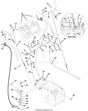
When it comes to maintaining and repairing machinery, understanding how its components fit together is essential. A clear representation of the individual elements helps users quickly identify parts and troubleshoot issues. By studying these illustrations, you can gain a deeper understanding of the overall structure, which allows for more effective servicing and repairs.
Maintenance and repair manuals often include detailed visuals that break down the equipment’s internal and external components. These guides can be invaluable when you need to locate a specific piece or when you are unsure of the function of a particular element. They offer clarity and precision, making the entire maintenance process more straightforward.
Proper knowledge of these technical diagrams can also help prevent errors during repairs, saving time and reducing the risk of damaging the equipment. Whether you are a professional or an enthusiast, learning to read these illustrations is a crucial step in ensuring your machinery operates at its best.
Understanding the Equipment Breakdown
To effectively maintain or repair machinery, it is essential to familiarize yourself with its internal components and how they interconnect. A clear representation of these elements provides an organized view of the structure, allowing you to identify the right pieces and their functions. These visual guides simplify the complex relationships between parts, ensuring you understand where each component fits within the larger system.
These detailed illustrations serve as a roadmap, offering insight into the overall design. By following the breakdown, users can quickly locate specific elements, identify possible faults, and understand how different sections interact. This knowledge is vital for performing accurate repairs and avoiding mistakes that could lead to further damage.
Becoming proficient at interpreting these visual resources is a key skill for anyone involved in the upkeep of machinery. Whether you’re a novice or experienced technician, understanding the layout of these detailed visuals makes the repair process smoother and more efficient.
How to Read an Equipment Breakdown
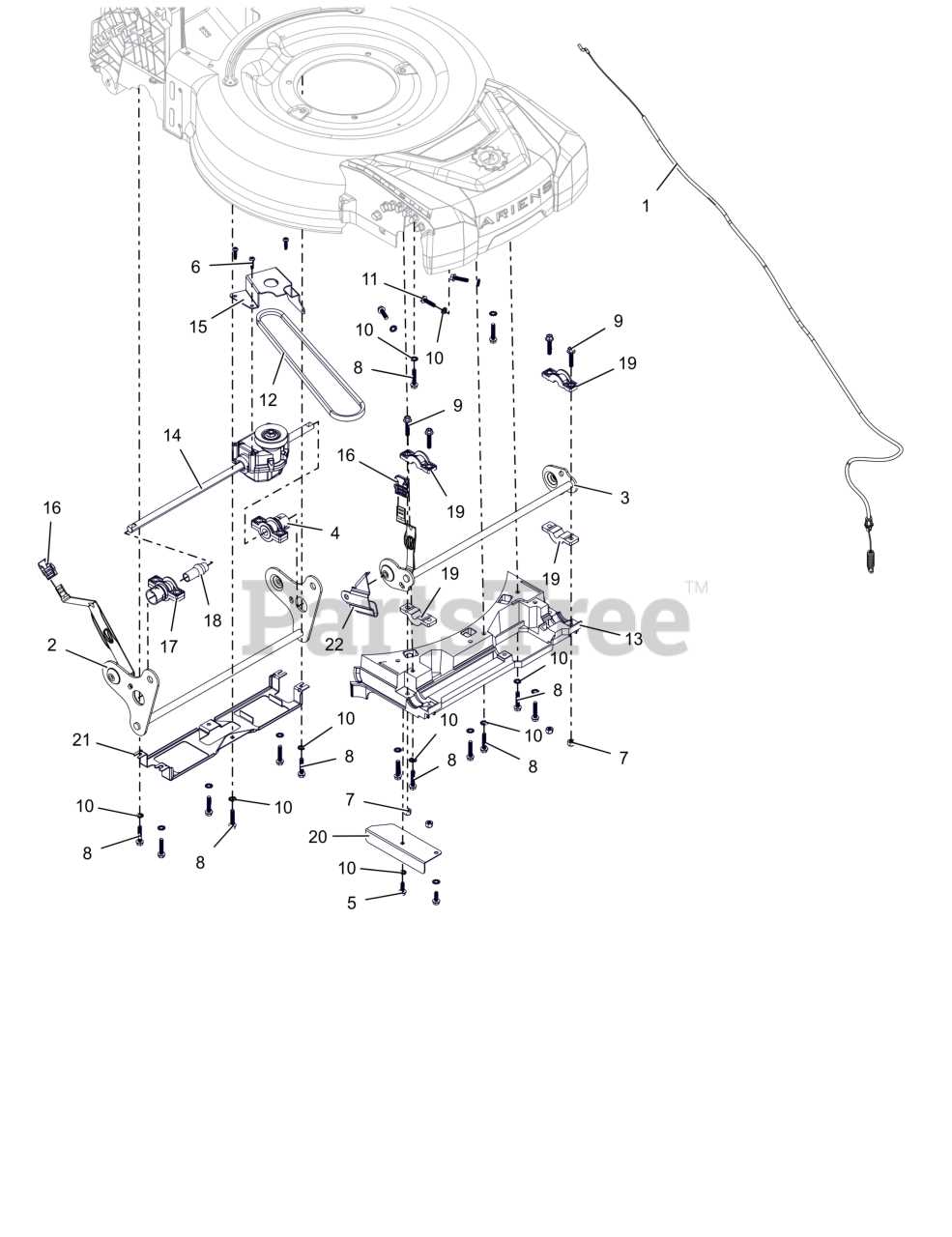
Interpreting technical illustrations of machinery is a critical skill for anyone involved in maintenance or repair. These visual guides often use labels, numbers, and lines to show how each element fits together within the overall structure. Understanding how to read these representations can help identify the right components and their placement, making the repair process more efficient.
Start by familiarizing yourself with the layout of the image. Components are typically arranged logically, often starting from the central or most important section, with other parts branching out from there. Pay attention to the numbering system used, as each number corresponds to a specific item or section that can be referenced for further details.
Check the accompanying legend or list for additional information. This will often provide further context, such as part numbers, descriptions, and other relevant data that may not be immediately obvious from the image alone. With practice, you’ll be able to quickly pinpoint which part is needed and how it connects to others in the machinery.
Common Issues Identified with Visual Guides
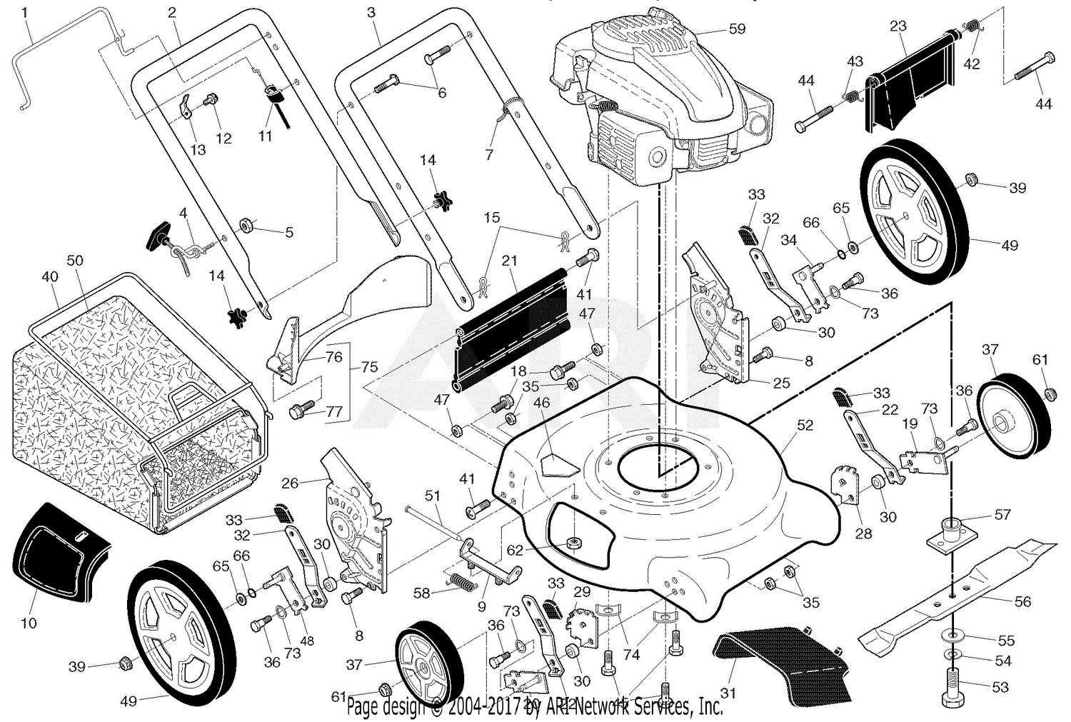
When working with technical illustrations, users may encounter several challenges that could make understanding the breakdown more difficult. These common issues often arise from unclear labeling, poor resolution, or missing details that leave essential information open to interpretation. Identifying and addressing these problems is crucial to ensure accurate repairs and maintenance.
One frequent issue is the lack of legible or sufficient labels, which can make it difficult to pinpoint the exact components needed for the task. Without clear references, it may be unclear which parts are required or how they interact with others. Another challenge is the resolution quality of the image. Low-quality visuals can blur the lines between parts, making it harder to identify components or understand their connections.
Another common problem occurs when the visual guide does not match the specific model in question. Variations in design can lead to confusion when the breakdown is not updated for the latest versions of equipment. This mismatch can result in incorrect part identification or improper repairs. Always ensure that the guide matches the exact model you are working on to avoid mistakes.