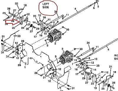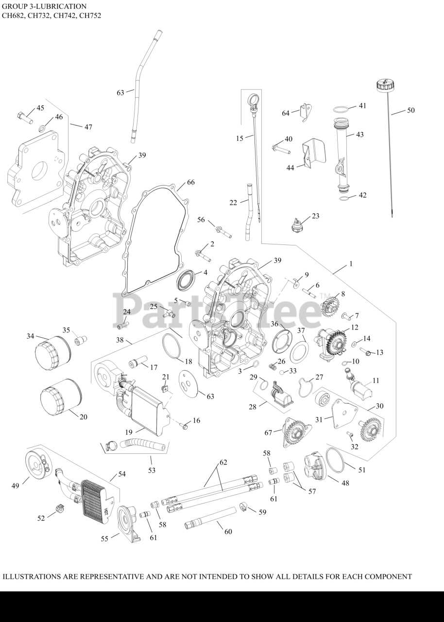
When maintaining any complex machinery, having a clear visual representation of its components is essential. Such a guide allows users to identify each part, understand its role, and make informed decisions during repairs or upgrades.
By breaking down the structure into its individual elements, the process becomes more manageable and less daunting. With an accurate guide, even intricate systems can be navigated with confidence.
Whether for routine maintenance or troubleshooting specific issues, having access to a comprehensive reference can greatly improve the efficiency of any repair task. This resource is designed to help users stay organized and prevent unnecessary complications.
Understanding the Key Components
Every mechanical system consists of various elements that work together to ensure smooth operation. Understanding these individual components is crucial for effective maintenance and troubleshooting. When each part is recognized for its function and placement, it becomes easier to manage repairs and replacements.
Core Functional Elements
The heart of any machine lies in its core functional components. These are the parts responsible for carrying out the primary tasks. By examining these elements closely, users can gain insight into how the system operates and where potential issues may arise.
Supporting and Auxiliary Components
In addition to the main functional parts, there are supporting components that help optimize performance and ensure longevity. These parts may not be as visible or essential to everyday operation but are critical for maintaining efficiency and preventing wear and tear over time.
How to Read the Schematic

Interpreting a schematic requires an understanding of how individual elements are represented and connected within the system. This visual guide provides valuable information about each component’s placement and how they interact with one another. Knowing how to read it correctly can save time during assembly, maintenance, or repairs.
Identifying Key Symbols and Labels
Each element on the schematic is represented by a unique symbol or label. Recognizing these symbols is essential to understanding the function of each part within the system. Familiarity with these representations allows for quick identification of the necessary components during repairs or upgrades.
Understanding the Connections
The lines and arrows in the schematic indicate how components are connected or how they work together. Understanding these connections helps in determining the flow of energy or movement within the system. Analyzing these relationships is key to diagnosing issues or performing effective maintenance.
Common Repairs Using the Schematic
Understanding how the system’s components are organized is crucial when it comes to repairing common issues. A detailed schematic helps identify faulty parts, enabling users to locate the problem quickly and make the necessary fixes. Whether dealing with minor malfunctions or more significant failures, knowing how to read this guide can simplify the process.
One of the most frequent repairs involves addressing worn or damaged elements that impact performance. By referencing the schematic, users can determine which components are responsible for the issue and replace them with precision.
Another common repair is fixing connections or alignments between parts that may have loosened or shifted over time. The schematic provides insight into how the components should be positioned, ensuring a more accurate repair and preventing further damage.