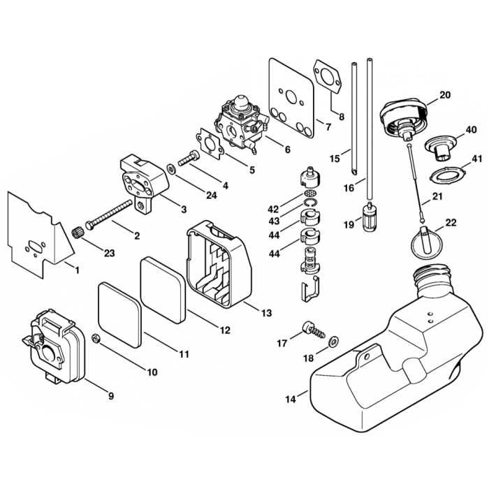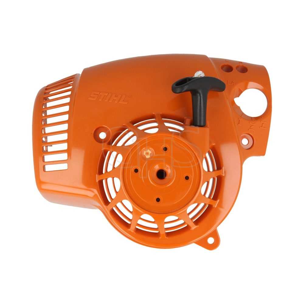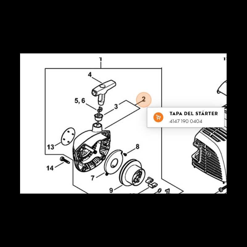
Understanding the layout and structure of equipment is crucial for efficient maintenance. With the right tools and knowledge, identifying individual parts becomes much easier, allowing for smoother repairs and upkeep. Whether you are a professional or a hobbyist, having a clear reference can make all the difference when restoring functionality to your tools.
Properly recognizing and understanding each part ensures that you are well-prepared to handle any issues that may arise. With detailed illustrations and thorough guides, it’s possible to diagnose problems quickly and accurately. This knowledge empowers users to not only address current issues but also to prevent future breakdowns through timely maintenance.
Exploring a well-organized breakdown helps clarify how each component interacts with others, providing insight into the assembly and disassembly process. Whether you’re replacing a worn-out element or troubleshooting an existing malfunction, this clarity can save both time and effort in the long run.
Understanding the Stihl SH86C Parts Layout
Every tool or machine is made up of several key components that work together to achieve its intended function. When performing maintenance or troubleshooting, understanding how each element is positioned and interacts with others is essential. A clear layout allows for easier identification of potential issues and accelerates the repair process.
Recognizing the core structure is the first step in any repair. By studying a well-organized overview of the tool’s layout, users can pinpoint specific components that might need attention. This understanding not only helps in replacing worn or damaged parts but also aids in reassembling the tool after service, ensuring everything is correctly aligned for optimal performance.
Knowing the relationships between the various elements enables users to see how each part supports the function of the whole machine. For example, understanding which components are responsible for the tool’s power or how airflow is managed can guide more effective repairs and improve overall efficiency. This level of comprehension ultimately empowers users to handle their tools with confidence and precision.
Key Components of the Stihl SH86C Model
To properly maintain and repair any tool, it is crucial to understand the essential elements that make up the machine. Each component plays a significant role in ensuring smooth operation, and knowing these elements can help users troubleshoot problems more effectively. Recognizing each key piece helps in both preventive maintenance and efficient repairs.
Engine and Power Mechanism
The engine serves as the powerhouse of the equipment, driving the performance of the tool. It is responsible for generating the necessary energy that powers all other components. Understanding its layout and function is essential for diagnosing performance issues, such as lack of power or stalling.
Airflow and Exhaust System
Efficient airflow is another critical aspect that affects the machine’s performance. Components such as the intake system and exhaust valves help regulate airflow and prevent overheating. Familiarity with this system can help prevent damage and ensure that the tool operates at optimal efficiency.
How to Use the Parts Diagram for Repairs

Having a detailed reference guide is crucial when performing maintenance or fixing a malfunctioning tool. By carefully studying a well-organized visual reference, users can identify the exact components that need attention, simplifying the repair process. Understanding how to navigate this guide is key to making repairs more efficient and preventing further damage to the equipment.
Identifying the Malfunctioning Component

Start by identifying the issue you’re experiencing with the equipment. A clear visual guide will highlight each component’s position, helping you locate the part in question. Once identified, you can determine if the part needs to be replaced or simply adjusted, avoiding unnecessary disassembly of other sections.
Step-by-Step Disassembly and Reassembly
Follow the layout step by step for both disassembly and reassembly. The diagram provides a clear order for removing and installing each component, ensuring that no crucial steps are missed. It also prevents mistakes that could occur when incorrectly reassembling the tool, helping you restore it to its optimal function.