Efficient operation of farming equipment relies heavily on understanding its intricate components. In this section, we will explore the various elements that make up a specific machine used for hay and crop processing, focusing on their functions and interconnections.
Recognizing each part and how it contributes to the overall performance is essential for maintaining the equipment in peak condition. This knowledge not only helps in troubleshooting but also ensures the longevity of the machine, reducing downtime during critical farming periods.
Maintenance practices and periodic inspections become much easier when one is familiar with how each component works. By breaking down the system into its key parts, we aim to provide a comprehensive guide that enhances your ability to care for and operate your machinery with confidence.
Understanding the John Deere 467 Baler
Farming machinery designed for collecting and compacting crop material plays a vital role in ensuring efficient processing. A well-constructed system that integrates various functional components allows for seamless operation, improving productivity in the field. This section will focus on understanding the machine’s core structure and how its elements work together to achieve optimal performance.
At the heart of this machine is a mechanism that helps gather loose material, compress it into manageable bundles, and secure the result. Each piece of equipment involved in this process contributes to enhancing efficiency, reducing labor efforts, and ensuring high-quality outcomes. Familiarizing yourself with how these elements interact is key to operating the machine effectively and addressing any operational challenges.
In the following sections, we will delve deeper into the features and functions of the system, highlighting its major components and their roles. Understanding these aspects can help with better maintenance and troubleshooting, ensuring that the equipment remains reliable throughout its use.
Key Components of the Baler System

Every machine involved in crop collection and compression relies on several key elements working in harmony. These components must function together smoothly to ensure proper operation, efficiency, and consistent results. Understanding the major parts of the system and their individual roles is essential for effective maintenance and troubleshooting.
Primary Components of the System
- Gathering Mechanism: Responsible for collecting the loose material from the field and feeding it into the compression chamber.
- Compression Chamber: Where the material is tightly packed into a compact form for easy handling and storage.
- Feeding System: Moves material into the chamber, ensuring consistent flow and uniform bales.
- Binding Mechanism: Secures the compressed material with twine or netting, preventing it from unraveling during transport.
Supporting Systems
- Drive System: Provides the necessary power to operate various components of the machine, ensuring smooth operation.
- Hydraulic System: Controls the movement of key parts, such as the compression chamber and binding mechanism, using fluid pressure.
- Control Panel: Allows the operator to adjust settings and monitor the machine’s performance during operation.
How to Read the Parts Diagram
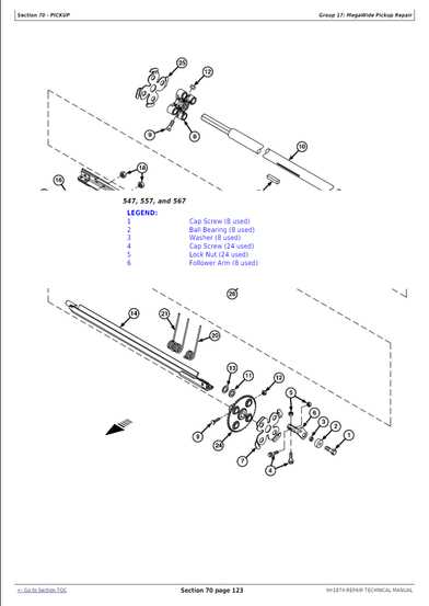
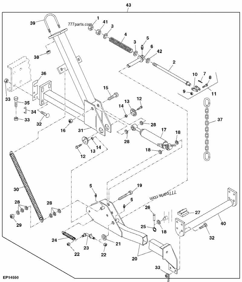
Understanding how to interpret technical illustrations is crucial for anyone working with complex machinery. These visual representations provide a detailed view of each component, showing how they are connected and function together. In this section, we will explore how to read and understand the key features of these illustrations for efficient maintenance and repairs.
First, it is important to familiarize yourself with the labels and numbers associated with each part. These identifiers correspond to specific components, allowing you to pinpoint and reference the right items for troubleshooting or replacement. Often, each part will have a unique number or code, making it easy to locate the exact replacement when needed.
Understanding the layout of the diagram is also essential. The components are typically arranged to show their position within the system, with arrows indicating movement or flow. By following these visual cues, you can better grasp how each part contributes to the overall operation of the equipment.
Lastly, knowing how to interpret additional notations–such as measurements, tolerances, or material specifications–will help you fully understand the diagram and ensure correct assembly or repairs. This knowledge is key to performing effective maintenance and ensuring the longevity of your equipment.
Maintenance Tips for John Deere 467
Regular upkeep of agricultural machinery ensures that it operates efficiently throughout the season, reducing the risk of breakdowns and costly repairs. In this section, we will provide essential maintenance advice to keep your equipment in peak condition. Proper maintenance not only extends the lifespan of your machine but also helps maintain its performance, ensuring that it consistently meets your operational needs.
Routine Checks and Cleaning
- Inspect key components: Regularly check the moving parts such as the feed system and compression mechanisms for signs of wear or damage.
- Clean regularly: Keep the system free from debris and dirt that can interfere with operation. Pay attention to the intake and exit points to avoid blockages.
- Lubrication: Ensure that all moving parts are properly lubricated to prevent friction and maintain smooth functioning.
Seasonal Maintenance Tasks
- Check hydraulic fluids: Monitor fluid levels and replace fluids as needed to ensure optimal system performance.
- Inspect belts and tension: Look for signs of wear and make sure that belts are properly tensioned to prevent slippage or breakage.
- Review safety mechanisms: Make sure that safety devices such as shields and emergency stops are in good working order to avoid accidents.