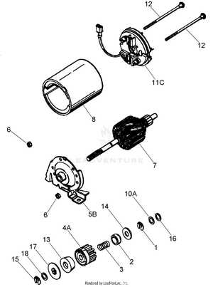
Having a clear visual representation of any mechanical system can significantly improve the process of maintenance and repairs. Identifying each element in a system allows for easier troubleshooting and part replacement. Knowing the layout of the system helps in managing the tools and resources needed for specific tasks.
Efficiently navigating through a system’s schematic ensures that you can quickly locate essential components and understand their connections. This step is crucial for anyone working on repairing or replacing different units within a device. Whether you’re a professional technician or a DIY enthusiast, mastering these visual guides simplifies the work.
By understanding how various elements interact within a system, one can plan repairs, replacements, and upgrades with confidence. This approach not only saves time but also reduces the chances of mistakes that could result in further damage or inefficiency.
Understanding the Lv195ea Parts Structure
Every system, whether mechanical or electronic, is composed of various interconnected components that work together to achieve a specific function. The layout of these components is crucial for identifying how each part contributes to the overall operation. Knowing the structure of the system allows for effective maintenance, repair, and optimization.
Key Elements in the System

The core parts of the system are usually divided into distinct sections, each responsible for a specific task. These parts include structural, functional, and support elements that are all interconnected. By analyzing these areas, one can understand the flow of operation and how to approach fixing any issues.
- Structural components – form the framework that supports the entire system.
- Functional parts – responsible for performing tasks, such as motors, sensors, or circuits.
- Support elements – help in maintaining stability, such as brackets, covers, and connectors.
How the Components Interact
The efficiency of a system depends on how well each part functions in harmony with others. The interaction between components must be understood to ensure that replacements or adjustments do not disrupt the overall operation. A thorough understanding of this relationship helps in pinpointing faulty sections and making precise repairs.
- Check compatibility before replacing any part.
- Ensure connections are secure and intact to avoid malfunctions.
- Consider the impact of each component on the system’s efficiency.
Identifying Key Components in the Diagram
Understanding the layout of a system is essential for effectively identifying its individual elements. Each component plays a specific role, and recognizing these parts is crucial for performing maintenance, troubleshooting, or upgrades. Being able to locate and name these parts allows for precise interventions and reduces the chance of errors during repairs.
When analyzing a system’s layout, focus on the most vital components that affect its operation. These often include power sources, control units, and connectors that link various sections together. Knowing how each part interacts with others is key to ensuring everything functions smoothly.
- Power sources – crucial for providing energy to the system.
- Control units – manage the functions and operations within the system.
- Connectors – establish communication between different sections.
By following the structure outlined in the layout, one can easily identify malfunctioning components and replace them efficiently. Being familiar with the overall design simplifies finding the right part in the right location, making the maintenance process much more straightforward.
How to Use the Lv195ea Diagram Effectively
Utilizing a visual representation of a system is an essential skill for efficient troubleshooting and repairs. The ability to read and interpret the layout accurately enables quick identification of faulty sections and ensures that repairs are done properly. Knowing how to navigate through the schematic is a key factor in making the process smoother and more precise.
Step-by-Step Approach
Start by carefully examining the entire layout. Understand the general flow and relationships between the components. Once you have a grasp of the overall structure, focus on the areas that may be causing issues. Marking specific sections on the diagram can help you concentrate on critical points during maintenance.
- Familiarize yourself with the overall layout first.
- Identify the connections and paths between components.
- Pinpoint the key sections that require attention or replacement.
Best Practices for Efficient Use
Labeling components on the schematic can significantly enhance your ability to quickly locate and address any malfunctions. Use annotations to highlight important areas for future reference. This will save time and ensure that you do not miss any essential steps.
- Always double-check the orientation and connections.
- Use a color-coded system for easy identification of parts.
- Consult the layout frequently throughout the repair process.