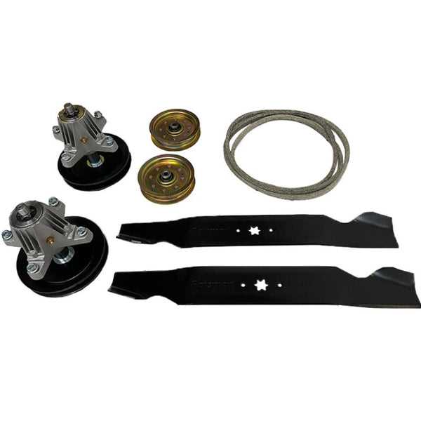
When maintaining or repairing your lawn mower, understanding its internal structure is essential. A visual representation of the mower’s various sections can help you pinpoint any issues, ensuring a smooth and efficient repair process. This guide will assist you in recognizing each part and its function.
Having a clear understanding of how different components interact with each other can significantly improve your ability to troubleshoot common problems. Whether you are replacing worn-out parts or upgrading certain features, knowing what each piece does is crucial for making informed decisions during maintenance.
In the following sections, we will explore how to navigate through the visual guide, identify key elements, and use this information to ensure your machine runs at its best. By the end, you’ll have a clearer idea of how to approach repairs and replacements with confidence.
Understanding the Lawn Mower Schematic
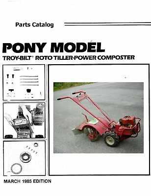
Having a clear visual map of the internal components of your lawn mower allows for easier identification of individual parts and their interconnections. This schematic serves as a valuable tool when you’re troubleshooting or performing maintenance. By understanding how each section is laid out, you can better assess the condition of your mower and determine what needs attention.
The diagram offers a detailed view of the machine’s structure, highlighting key elements such as the engine, drive system, and control mechanisms. It shows the relationship between these components and how they work together to ensure proper functioning. Familiarizing yourself with the layout helps you to spot any potential problems quickly and accurately.
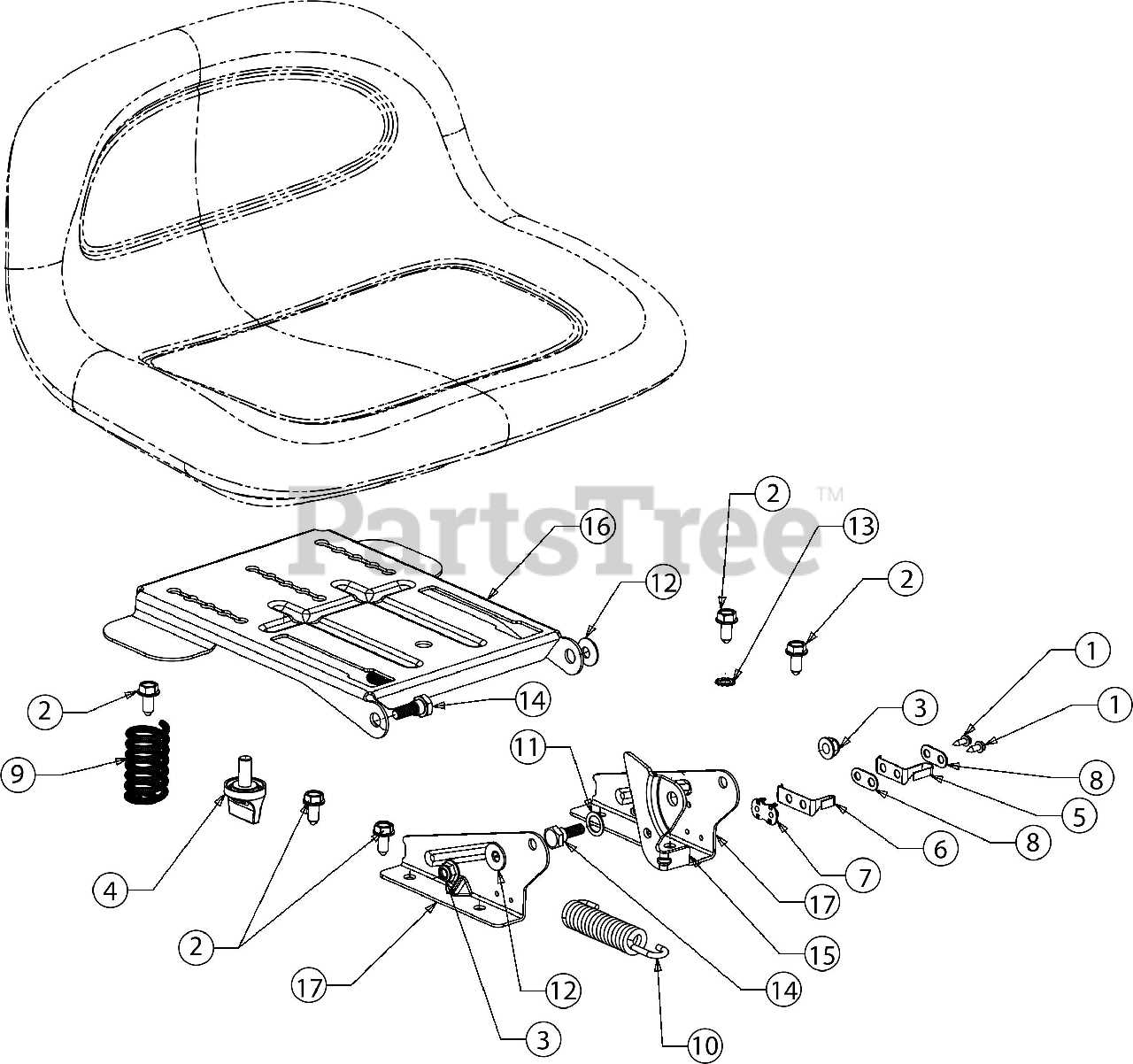
Once you understand how to read the visual guide, it becomes a powerful resource for making informed decisions about repairs or replacements. Whether you’re looking to fix an issue or perform routine maintenance, this map provides the clarity needed to navigate the system efficiently.
Identifying Key Components of Your Lawn Mower
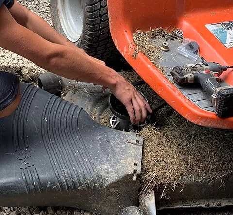
Understanding the major elements of your lawn mower is crucial for effective maintenance and repair. The various sections work together to ensure smooth operation, and knowing what each component does helps you troubleshoot issues and replace worn parts. Familiarizing yourself with these key components can save you time and effort when caring for your equipment.
One of the most important sections to identify is the engine, which serves as the powerhouse of your mower. This part generates the energy needed for operation, and its condition is vital for performance. Next, the drive system, which includes the wheels and gears, controls the movement of the mower across your lawn. Ensuring that these parts are functioning correctly is essential for smooth operation.
Additionally, the cutting mechanism, typically consisting of blades or a similar device, plays a critical role in lawn care. It’s important to regularly check for damage or dullness to maintain the quality of your lawn’s appearance. Other key elements like the fuel system, handles, and safety features also contribute to overall efficiency, making it essential to recognize them during your maintenance routine.
How to Use the Visual Guide for Repairs
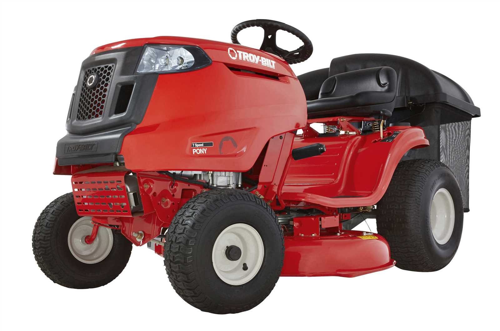
Using a visual guide for repairs allows you to clearly see the layout of your machine and helps you identify where each component is located. This tool is invaluable when replacing damaged or worn-out parts, as it shows the exact positions and connections between the various sections. By following the guide, you can ensure that you are addressing the right issues without wasting time.
To begin, locate the part or section that is causing the problem. The schematic will provide a clear reference, highlighting each component’s specific role within the system. This makes it easier to understand how parts interact with one another and which pieces need attention.
Next, use the guide to find the correct replacement or repair procedure for the faulty component. Whether you are tightening bolts, replacing a worn part, or adjusting settings, the visual map helps you understand the steps involved. Always double-check the diagram to ensure that you are working with the right part and that everything is reassembled properly after the repair.