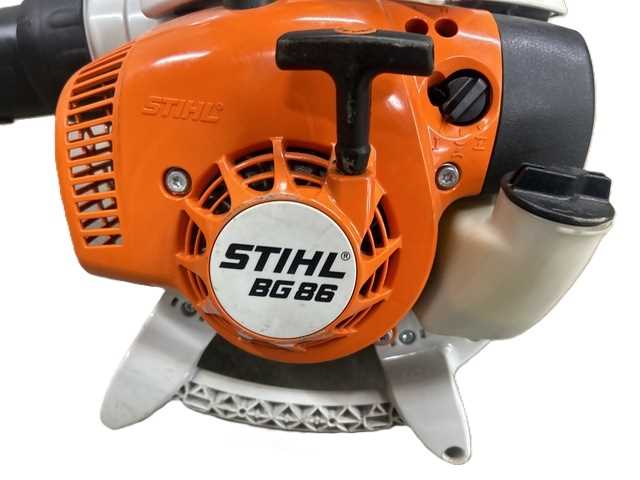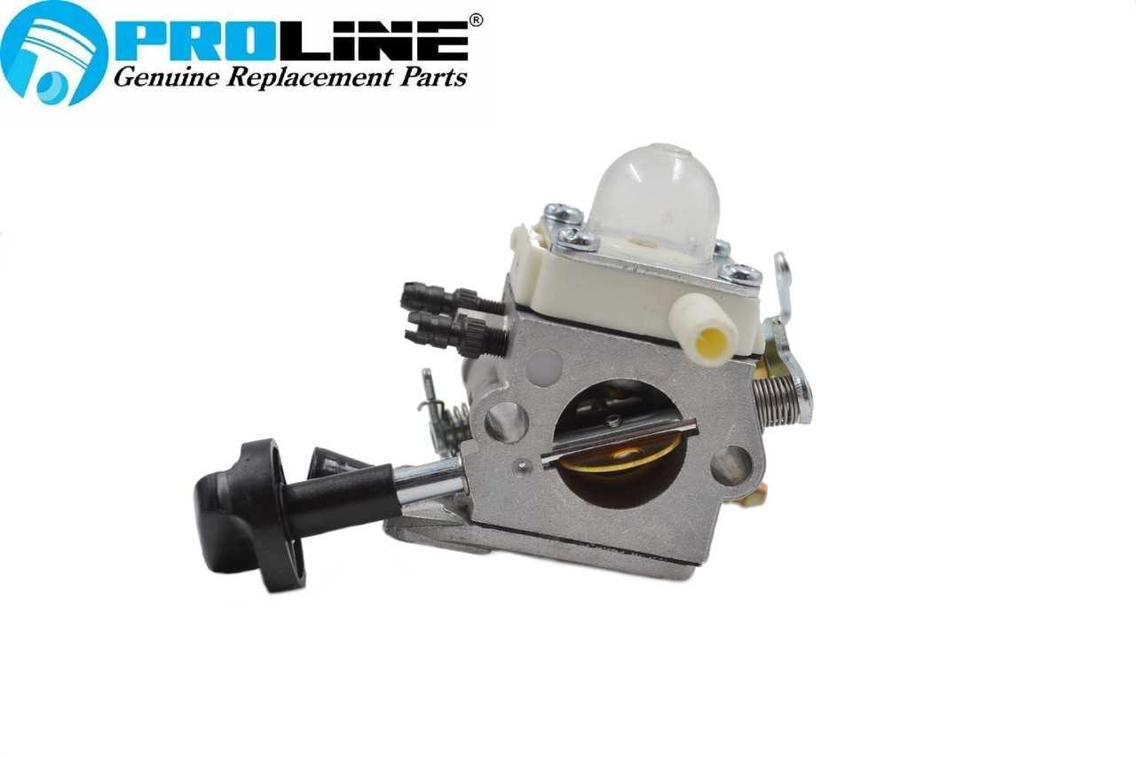
When it comes to maintaining or repairing outdoor equipment, understanding how its individual elements fit together is crucial. Proper knowledge of the device’s internal structure allows for efficient troubleshooting and precise fixes, ensuring optimal performance. Whether you’re a professional or a DIY enthusiast, having access to detailed schematics is invaluable for effective repairs.
Accurate identification of each component plays a key role in maintenance tasks. Recognizing how different parts interact with one another can help prevent unnecessary replacements and ensure a smoother repair process. This detailed breakdown will guide you through the essential elements that make up a common handheld blower, allowing you to approach any issue with confidence.
By becoming familiar with how these devices are assembled and understanding each component’s function, you can improve your troubleshooting skills and extend the lifespan of your equipment. Knowledge is the foundation for better maintenance and fewer unexpected repairs, ultimately saving you both time and money.
Understanding Blower Components Layout

Every complex machine consists of various components that work together to achieve optimal performance. Gaining an understanding of how these elements are organized within the device can help users recognize their purpose and how they contribute to the overall function. Whether it’s for maintenance or troubleshooting, a clear grasp of how the internal parts are laid out is essential for making informed decisions during repairs.
In a handheld blower, the configuration of its key elements plays a vital role in its ability to function efficiently. From the engine assembly to the airflow system, each component is positioned in a way that enhances performance and reliability. Recognizing these relationships is important for identifying potential issues and ensuring that repairs are focused on the right areas.
By examining the layout carefully, users can better anticipate how to access specific parts when servicing the equipment. This knowledge provides confidence in performing routine maintenance or resolving more complex malfunctions, helping to keep the machine in peak condition for longer. Understanding the arrangement of these vital parts makes the repair process smoother and more effective, reducing the need for trial and error.
Key Components of the Blower
To ensure that a blower operates effectively, it must have several essential components that work in harmony. These elements are responsible for generating power, creating airflow, and providing control over the device’s operation. Understanding each of these vital components helps users manage the equipment and address issues when they arise.
Among the most important parts are the engine, which powers the machine, and the fan or impeller, which drives the airflow. The housing encases these internal systems and protects them from damage. Additionally, the fuel system and ignition system are critical for starting and maintaining consistent performance during operation. Without these key components functioning properly, the blower may not perform as expected, and troubleshooting may become necessary.
Familiarity with these core components allows users to troubleshoot more efficiently and perform routine maintenance. By knowing where these elements are located and how they interact, users can address any issues with greater precision and avoid unnecessary repairs.
How to Use the Parts Diagram Effectively
Using a detailed schematic or layout of a device can greatly enhance the efficiency of both repairs and maintenance. It allows users to quickly identify the components that need attention and to understand how different parts fit together. With this tool, you can avoid confusion during disassembly or reassembly, ensuring a smoother process overall.
Identify Key Components
Before beginning any work, carefully study the layout to familiarize yourself with the essential parts. This step is crucial for pinpointing which components are most likely to wear out or become damaged over time. Knowing where each part is located helps streamline the repair process and reduces the likelihood of mistakes.
Follow Step-by-Step Instructions
Once you’re familiar with the layout, use the schematic as a guide to dismantle or assemble the device. The visual representation ensures you don’t skip any steps, and it provides clarity on how to access and replace specific components. Referencing the diagram throughout the process helps maintain order and minimizes the risk of missing critical parts.