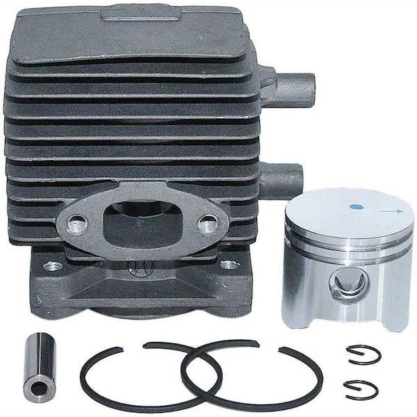
Maintaining and repairing your outdoor equipment can seem challenging without proper guidance. Knowing the structure and function of each component is crucial for efficient troubleshooting and replacement. With a detailed visual reference, you can easily identify the necessary parts and understand how they fit together. This guide aims to provide clear, step-by-step insights into the most important aspects of your machine.
When it comes to ensuring the longevity and performance of your device, understanding its internal mechanisms is key. Visual aids allow you to pinpoint damaged or worn-out parts, enabling you to make informed decisions about repairs or replacements. This article will help you navigate the process with ease, ensuring that your tool remains in optimal working condition.
Understanding the Layout of Your Tool’s Components

Every outdoor power equipment device consists of a variety of interrelated components that work together to ensure smooth operation. A clear understanding of how these elements are organized and connected is essential for anyone looking to perform maintenance or repairs. By examining the layout of the device, you can identify where each part fits and how they contribute to the overall performance.
The arrangement of parts in your equipment is designed to maximize efficiency and functionality. Each piece plays a specific role, from the engine to the handle, and knowing the function of each can help you identify potential issues faster. This layout not only makes repairs easier but also allows you to ensure proper alignment and function after performing any maintenance tasks.
Identifying Key Components in the Equipment Layout
Recognizing the essential parts of your outdoor tool is a fundamental step in maintaining its performance. Each component plays a vital role in the functioning of the device, and understanding their specific positions and relationships can help simplify troubleshooting. By focusing on the most important elements, you can quickly diagnose issues and perform necessary repairs or replacements.
Critical Engine Components
The engine is the heart of the tool, and several parts work together to keep it running smoothly. Key components such as the spark plug, air filter, and fuel system must be in optimal condition for the engine to function efficiently. Identifying these critical elements within the layout will allow you to focus on potential problem areas during inspections and maintenance tasks.
Handle and Control Mechanisms
The handle and control systems are vital for comfort and proper operation. Identifying these components, such as the throttle, trigger, and safety mechanisms, ensures that the operator has full control over the tool’s functions. A well-maintained handle system contributes to both safety and ease of use, making it an essential part to examine during any routine check-ups.
How to Use Equipment Layout Effectively
Utilizing a detailed layout of your tool can greatly enhance your ability to perform accurate repairs and maintenance. By referring to a well-organized visual guide, you can pinpoint the exact location of each component and understand how they interconnect. This allows for easier identification of damaged or worn parts, making your repair process more efficient and precise.
To make the most of this visual reference, start by familiarizing yourself with the overall structure of the device. Focus on the main sections, such as the engine, handle, and operational controls. Once you understand the general layout, you can more effectively locate specific components, ensuring that your maintenance tasks are targeted and thorough.